
User's Manual

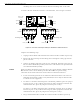


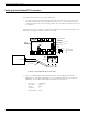
Table Of Contents
- 95 Series RFID System User’s Guide
- Table of Contents
- List of Figures
- Preface
- Introduction
- Reader R95 Installation and Connections
- Exciter E95 Installation and Connections
- Power Supply TRM95 Installation and Connection
- Configuration and Operation
- Before You Begin
- General Procedure Rules
- Setting Up the Reader/PC Connection
- Reader’s Power-up Sequence
- Learning Procedure (Optional)
- Resetting the Reader
- Checking the Reader’s Basic Parameters
- Setting Up the Exciter’s Address
- LF Transmitter Output
- Configuring the Reader
- Setting Up the Carrier Threshold
- Setting Up the Exciter’s Test-Tag
- Setting Up the Real Time Clock
- Configuring the Reader’s Application Parameters
- Configuring the Reader’s Network Parameters
- Storing the Reader’s Configuration
- Reader - Final Setup
- 95 Series RFID System - Final Test
- Programming and Testing the Transponder T95
- Troubleshooting
- Specifications
- Transponder T95 Messages
- Excitation Modes
- Reader Software Upgrade Procedure
- Glossary
- Index

Connecting the RS-485 Communication Lines
3-4 Exciter E95 Installation and Connections
incoming cable to one connector and the RS-485 outcoming cable to the other.
To connect RS-485 communication lines to the EXT95SC, refer to Figure 3-2 below.
Figure 3-2: Connections and Jumpers Settings for the RS-485 Communication Lines
Complete the following steps:
1. Unplug terminal blocks TB4 and TB6 from connectors TB3 and TB5 respectively.
2. Run the RS-485 incoming and outcoming cables through the cable grips into the
plastic enclosure.
3. Connect the RS485_CMD line to pins A1, B1, and RS485_SGN line to the pins A2,
B2 on terminal block TB4 (or TB6). Connect the cable shield to the pin marked G
on terminal block TB4 (or TB6).
Caution Before installing the RFID System, label the 2 wires on the RS485_CMD line A1 and
B1; label the 2 wires on the RS485_SGN line A2 and B2.Keepthisnaming
convention for all connections made on these RS-485 communication lines.
4. Set the terminating load for the each RS-485 communication line. The ends of a
multidrop-network line could be easily identified, because only one RS-485 cable
is connected to the equipment.
5. To connect a 100 ohm terminating load to the RS485_CMD line, place the jumper
P1 between pins 1-2 of J1. When connecting any other equipment to this RS-485
communication line, place the jumper P1 between pins 2-3 of J1.
To connect a 100 ohm terminating load to the RS485_SGN line, place the jumper
P2 between pins 1-2 of J2. When connecting any other equipment to this RS-485
communication line, place the jumper P2 between pins 2-3 of J1.
6. Plug terminal blocks TB4 and TB6 into connectors TB3 and TB5 respectively.
J2
TB6
RS485RS485
TB4
A1
B1
A2
B2
A1 B1 A2
B2
J1
P1
Load
Open
1
G G
Exciter Slave EXT95SC
1
P2
Load
Open
RS485_CMD
Termination
RS485_SGN
Termination
A1
B1
A2
B2
RS485_CMD
RS485_SGN
B1
A1
RS485_CMD
B2
A2
RS485_SGN
Outcoming cable
Incoming cable