
User's Manual

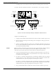
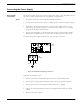


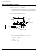
Table Of Contents
- 95 Series RFID System User’s Guide
- Table of Contents
- List of Figures
- Preface
- Introduction
- Reader R95 Installation and Connections
- Exciter E95 Installation and Connections
- Power Supply TRM95 Installation and Connection
- Configuration and Operation
- Before You Begin
- General Procedure Rules
- Setting Up the Reader/PC Connection
- Reader’s Power-up Sequence
- Learning Procedure (Optional)
- Resetting the Reader
- Checking the Reader’s Basic Parameters
- Setting Up the Exciter’s Address
- LF Transmitter Output
- Configuring the Reader
- Setting Up the Carrier Threshold
- Setting Up the Exciter’s Test-Tag
- Setting Up the Real Time Clock
- Configuring the Reader’s Application Parameters
- Configuring the Reader’s Network Parameters
- Storing the Reader’s Configuration
- Reader - Final Setup
- 95 Series RFID System - Final Test
- Programming and Testing the Transponder T95
- Troubleshooting
- Specifications
- Transponder T95 Messages
- Excitation Modes
- Reader Software Upgrade Procedure
- Glossary
- Index

Connecting the Power Supply
Exciter E95 Installation and Connections 3-5
Connecting the Power Supply
Power Supply
Connections
The Exciter requires an 22 Vac or 23 to 28 Vdc power source, and a maximum current
of 0.5 A. For more information, refer to Appendix A, Specifications.
Notes 1. The power connector is located on the EXT95SC assembly.
2. Useanelectricalwirewithatleasta16AWGgaugetoconnectthepowersupply.
3. The Exciter’s main ground connection is on the power supply connector. It is
indicated by the ground symbol. Use an electrical wire with at least a 16 AWG
gauge for the main ground connection.
4. To power the EXT95SC, we recommend using Lyngsoe’s Power Supply, model
TRM95/120V or TRM95/230V, as required by the local AC power line voltage.
To connect the power supply to the Exciter, refer to Figure 3-3 below.
Figure 3-3: Exciter E95 Power Supply Connections
Complete the following steps:
1. Remove terminal block TB8 from connector TB7 on the EXT95SC board.
2. Run the power supply cable through the cable grip into the plastic enclosure.
3. Connect power wires to the TB8 pins marked with the “~”symbol.
4. Connect the main ground connection to the TB8 pin marked with the ground
symbol.
5. Switch on the power supply.
Exciter Slave EXT95SC
~
~
TB8
POWER
TB10
22Vac 22Vac