
User's Manual

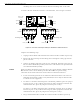
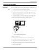


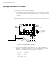
Table Of Contents
- 95 Series RFID System User’s Guide
- Table of Contents
- List of Figures
- Preface
- Introduction
- Reader R95 Installation and Connections
- Exciter E95 Installation and Connections
- Power Supply TRM95 Installation and Connection
- Configuration and Operation
- Before You Begin
- General Procedure Rules
- Setting Up the Reader/PC Connection
- Reader’s Power-up Sequence
- Learning Procedure (Optional)
- Resetting the Reader
- Checking the Reader’s Basic Parameters
- Setting Up the Exciter’s Address
- LF Transmitter Output
- Configuring the Reader
- Setting Up the Carrier Threshold
- Setting Up the Exciter’s Test-Tag
- Setting Up the Real Time Clock
- Configuring the Reader’s Application Parameters
- Configuring the Reader’s Network Parameters
- Storing the Reader’s Configuration
- Reader - Final Setup
- 95 Series RFID System - Final Test
- Programming and Testing the Transponder T95
- Troubleshooting
- Specifications
- Transponder T95 Messages
- Excitation Modes
- Reader Software Upgrade Procedure
- Glossary
- Index

UHF Transmitter - Direct Control (Optional)
3-6 Exciter E95 Installation and Connections
6. Check the voltage on the terminal block TB8 (between pins 1-3).
7. Plug terminal block TB8 into connector TB7.
8. Re-check the voltage in Step 6.
9. Check whether the voltage between pins 1 and 2 on terminal block TB10 is
5.0 ± 0.2 V.
10. Switch off the power supply.
UHF Transmitter - Direct Control (Optional)
The UHF transmitter can be also switched on using a hardware control, by creating a
a short between pins 1-2 on terminal block TB10. After this is done, the UHF
transmitter will start transmitting the pre-programmed messages and then stop. To
startanothertransmission,thecontactmustbeopenedandthenclosedagain.
The location of terminal block TB10 on the EXT95SC board is shown in Figure 3-3.
Assembling Other Models of Exciters
Lyngsoe provides other models of Exciters with different antenna frame sizes for
particular installations. As an example, see Exciter E95S (P/N 600647). For
mechanical assembling and electrical connections, use a similar procedure as
described in the previous paragraphs and drawing M900113.