
User's Manual

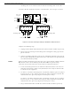
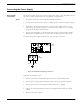


Table Of Contents
- 95 Series RFID System User’s Guide
- Table of Contents
- List of Figures
- Preface
- Introduction
- Reader R95 Installation and Connections
- Exciter E95 Installation and Connections
- Power Supply TRM95 Installation and Connection
- Configuration and Operation
- Before You Begin
- General Procedure Rules
- Setting Up the Reader/PC Connection
- Reader’s Power-up Sequence
- Learning Procedure (Optional)
- Resetting the Reader
- Checking the Reader’s Basic Parameters
- Setting Up the Exciter’s Address
- LF Transmitter Output
- Configuring the Reader
- Setting Up the Carrier Threshold
- Setting Up the Exciter’s Test-Tag
- Setting Up the Real Time Clock
- Configuring the Reader’s Application Parameters
- Configuring the Reader’s Network Parameters
- Storing the Reader’s Configuration
- Reader - Final Setup
- 95 Series RFID System - Final Test
- Programming and Testing the Transponder T95
- Troubleshooting
- Specifications
- Transponder T95 Messages
- Excitation Modes
- Reader Software Upgrade Procedure
- Glossary
- Index

Before you Begin
Power Supply TRM95 Installation and Connection 4-1
Chapter 4
Power Supply TRM95 Installation and Connection
This chapter explains how to:
• Install the Power Supply
• Make the input line and output connections
All data provided in this chapter apply to both Power Supply models TRM95/120V
(P/N 600579) and TRM95/230V (P/N 600626).
Before you Begin
Before installing the Power Supply:
• Read Chapter 4, Setup Guidelines in the 95 Series RFID System Technical Guide.
• Have at your disposal, the complete approved documentation describing the RFID
System configuration, equipment location, and wiring distances between
equipment (see the Site Survey Documentation).
• Check whether the mechanical supports for the Power Supply is installed on the
site according to the documentation.
• Check whether all cables are installed on the site according to the documentation
(type, protection, routing, etc.).
• Check whether the Power Supply unit has the correct rating (120V or 230V) that
is suitable for the local AC power lines voltage.
Tools To install the Power Supply, you will need the following tools:
• Phillips screwdriver size # 1)
• Slotted screwdriver 2mm
Installing Power Supply TRM95
For mechanical details, refer to the Power Supply assembly drawing.
Placement The Power Supply unit can be installed either horizontally or vertically, but must be
secured against its mechanical support with 4 screw (dia. 1/8"). It must be installed in
such a way that the front is easily accessible and visible for inspection. This unit is
designed for indoor use only. You should avoid installing the Power Supply unit in
locations where there is water or excessive humidity. To reduce the risk of
overheating, avoid exposing the Power Supply unit to direct sunlight or near any
heat-emitting devices, such as a room heater or a stove.