
User's Manual


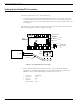
Table Of Contents
- 95 Series RFID System User’s Guide
- Table of Contents
- List of Figures
- Preface
- Introduction
- Reader R95 Installation and Connections
- Exciter E95 Installation and Connections
- Power Supply TRM95 Installation and Connection
- Configuration and Operation
- Before You Begin
- General Procedure Rules
- Setting Up the Reader/PC Connection
- Reader’s Power-up Sequence
- Learning Procedure (Optional)
- Resetting the Reader
- Checking the Reader’s Basic Parameters
- Setting Up the Exciter’s Address
- LF Transmitter Output
- Configuring the Reader
- Setting Up the Carrier Threshold
- Setting Up the Exciter’s Test-Tag
- Setting Up the Real Time Clock
- Configuring the Reader’s Application Parameters
- Configuring the Reader’s Network Parameters
- Storing the Reader’s Configuration
- Reader - Final Setup
- 95 Series RFID System - Final Test
- Programming and Testing the Transponder T95
- Troubleshooting
- Specifications
- Transponder T95 Messages
- Excitation Modes
- Reader Software Upgrade Procedure
- Glossary
- Index

Connecting Equipment to the Power Supply Unit
4-3 Power Supply TRM95 Installation and Connection
Connecting Equipment to the Power Supply Unit
The Power SUpply unit has 2 separate outputs (12Vac/1A and 22Vac/2A) to power up
separate RFID equipment as Readers R95 and Exciters E95. These voltages are
available for connecting an external cable on the Power Supply’s internal terminal
block and is clearly marked.
Attention Do not exceed the load ratings specified for each output: 1A for the 12Vac, and 2A for
the 22Vac. On the 22Vac source, the 2 terminal blocks are connected in parallel for
each output terminal. Always use a 3-wire cable to connect the equipment to the
Power Supply unit. Always connect the ground wire of each cable to the terminal
block that is indicated by
Connecting the AC Mains Supply
Connect the power lines cable to the internal terminal block of the Power Supply unit
as follows:
• Live(phase)-totheterminalmarkedL
• Neutral - to the terminal N
• Ground - to the terminal marked
For more information, see Chapter 8, Power Supply Assembly Drawings.
IMPORTANT Before you connect power to the Power Supply unit, re-check the following:
• The Power Supply model and rating against the installation plan and line voltage
• The Power Supply fuse rating
• All cable connections to the Power Supply’s internal terminal block
• All cable access into the Power Supply’s enclosure, making sur that they are
properly secured and protected.