
User's Manual
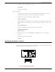
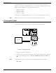

Table Of Contents
- 95 Series RFID System User’s Guide
- Table of Contents
- List of Figures
- Preface
- Introduction
- Reader R95 Installation and Connections
- Exciter E95 Installation and Connections
- Power Supply TRM95 Installation and Connection
- Configuration and Operation
- Before You Begin
- General Procedure Rules
- Setting Up the Reader/PC Connection
- Reader’s Power-up Sequence
- Learning Procedure (Optional)
- Resetting the Reader
- Checking the Reader’s Basic Parameters
- Setting Up the Exciter’s Address
- LF Transmitter Output
- Configuring the Reader
- Setting Up the Carrier Threshold
- Setting Up the Exciter’s Test-Tag
- Setting Up the Real Time Clock
- Configuring the Reader’s Application Parameters
- Configuring the Reader’s Network Parameters
- Storing the Reader’s Configuration
- Reader - Final Setup
- 95 Series RFID System - Final Test
- Programming and Testing the Transponder T95
- Troubleshooting
- Specifications
- Transponder T95 Messages
- Excitation Modes
- Reader Software Upgrade Procedure
- Glossary
- Index

Reader’s Power-up Sequence
Configuration and Operation 5-3
Reader’s Power-up Sequence
To verify the Reader’s power-up sequence, do the following:
1. Turn on the power supply to the Reader.
2. Referring to Figure 5-1, check whether the relay on the MBD95 board
immediately clicks, and the green POWER LED is on.
3. Check whether the Reader performs the following power-on test sequence: the red
DATA LED on the MBD95 board remains ON for 6-7 seconds. Afterwards, the
following sign-on message is displayed on the PC’s screen:
DISYS CRM-95 READER (c)Copyright DISYS Corporation 1989-1996.
Notes 1. If you did not assign a System Code identification number (SC) to the Reader, the
DATA LED will flash On and Off at a rate of 1.4 Hz. To set the System Code, type:
ISC=[your SC]<Enter>
2. If a string of unrecognizable characters appears on the PC’s screen, it means that
the communication link between the Reader and the PC is not set properly. Run
the Learning Procedure, as described below, to establish the correct settings.
Learning Procedure (Optional)
This a special mode of operation, specifically designed to allow a Reader to
communicate with the PC to which it is attached, by adapting itself to the serial frame
format that the PC is using.
ToforcetheReaderintothelearning mode,followthestepsbelow.(SeeFigure5-1).
1. Press the RESET button once.
2. Verify whether the DATA LED flashes at a rate of 2 Hz. This means that the
Reader is in the learning mode, and is waiting to determine the frame format sent
by the PC.
3. Send a few characters to the Reader, for example, LYNGSOE.
4. When the learning process is finished, the DATA LED will start flashing at 1.4 Hz
rate and the following message will be displayed on the PC:
Learned: rate, parity, bits
where:
rate: is the serial data rate (baud) expressed as a numeric value, for example,19200.
parity: is a single character that reports the parity bit: N for no parity, Y for parity.
bits: is a single digit (7 or 8) that reports the number of bits per character.
5. Check the values of the Reader’s current serial communication configuration by