
User's Manual
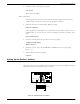
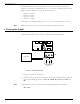

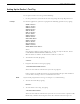
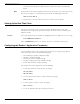
Table Of Contents
- 95 Series RFID System User’s Guide
- Table of Contents
- List of Figures
- Preface
- Introduction
- Reader R95 Installation and Connections
- Exciter E95 Installation and Connections
- Power Supply TRM95 Installation and Connection
- Configuration and Operation
- Before You Begin
- General Procedure Rules
- Setting Up the Reader/PC Connection
- Reader’s Power-up Sequence
- Learning Procedure (Optional)
- Resetting the Reader
- Checking the Reader’s Basic Parameters
- Setting Up the Exciter’s Address
- LF Transmitter Output
- Configuring the Reader
- Setting Up the Carrier Threshold
- Setting Up the Exciter’s Test-Tag
- Setting Up the Real Time Clock
- Configuring the Reader’s Application Parameters
- Configuring the Reader’s Network Parameters
- Storing the Reader’s Configuration
- Reader - Final Setup
- 95 Series RFID System - Final Test
- Programming and Testing the Transponder T95
- Troubleshooting
- Specifications
- Transponder T95 Messages
- Excitation Modes
- Reader Software Upgrade Procedure
- Glossary
- Index

LF Transmitter Output
5-6 Configuration and Operation
The addresses must be sequential between 1 and 14. For example, if there are 4
Exciters, they must be assigned addresses 1, 2, 3, and 4. Use the S1 switch to set the
address to binary format. For example, in binary format:
•address1is0001
2
•address2is0010
2
•address3is0011
2
•address4is0100
2
If the switch is in the ON position, the bit is set to 1. Otherwise, the bit is set to 0.
Note Addresses 0000
2
and 1111
2
are reserved for special modes of operation.
LF Transmitter Output
To check the LF signal, refer to Figure 5-3 below, and do the following:
Figure 5-3: LF Signal Measurement
1. Connect the power to the Exciter.
2. Check the current parameter settings for the excitation mode and write down the
value of the following parameters: RCS, RES, REM, RET, HCC, HCS, HE0,and
HE1.
Note To determine the value of a parameter, for example, HE1,typethecommand:
HE1 <Enter>
E
x
c
i
t
e
r
S
l
a
v
e
E
X
T
9
5
S
C
TB2
ANT
GND
B
l
a
c
k
TAP
R
e
d
W
h
i
t
e
To LF Antenna
Terminal Block
Oscilloscope