
User's Manual
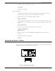
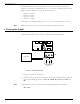

Table Of Contents
- 95 Series RFID System User’s Guide
- Table of Contents
- List of Figures
- Preface
- Introduction
- Reader R95 Installation and Connections
- Exciter E95 Installation and Connections
- Power Supply TRM95 Installation and Connection
- Configuration and Operation
- Before You Begin
- General Procedure Rules
- Setting Up the Reader/PC Connection
- Reader’s Power-up Sequence
- Learning Procedure (Optional)
- Resetting the Reader
- Checking the Reader’s Basic Parameters
- Setting Up the Exciter’s Address
- LF Transmitter Output
- Configuring the Reader
- Setting Up the Carrier Threshold
- Setting Up the Exciter’s Test-Tag
- Setting Up the Real Time Clock
- Configuring the Reader’s Application Parameters
- Configuring the Reader’s Network Parameters
- Storing the Reader’s Configuration
- Reader - Final Setup
- 95 Series RFID System - Final Test
- Programming and Testing the Transponder T95
- Troubleshooting
- Specifications
- Transponder T95 Messages
- Excitation Modes
- Reader Software Upgrade Procedure
- Glossary
- Index

LF Transmitter Output
Configuration and Operation 5-7
The Reader will respond with the parameter value, for example,
HE1=6
where 6 is the value for the HE1 parameter.
3. Set the Continuous DC Mode type of execution, by typing:
RCS=N <Enter>
RES=N <Enter>
REM=C <Enter>
RET=D <Enter>
Note If a parameter already has the wanted value (determined in Step 2), you do not have
to reset it.
4. Turn on the excitation field, by typing:
B<Enter>
Check the TAP voltage [V
TAP
] at the terminal block TB2 on the EXT95SC board
(see Figure 5-3) using an oscilloscope. The signal must be a continuous
unmodulated carrier of 128.25 kHz with a peak-to-peak amplitude of
V
TAP
=100±20V
pp
.
Note When more than one Exciter 95 is used to create a wider excitation zone, a magnetic
coupling can appear. The phenomenon is explained in Chapter 4, Setup Guidelines in
the 95 Series RFID System Technical Guide. The coupling generates an unwanted
amplitude modulation with a frequency of several Hertz, the modulation depth
depending directly on the coupling. The installer has to monitor the TAP signal and
adjust the position of the E95 frames to obtain a minimum unwanted modulation
depth. The installer can increase the distance between frames, level the frames in the
same plane, or place the frames with the shorter sides (1m) in parallel. The minimum
amplitude of V
TAP
due to unwanted modulation must be larger than 60V
pp
.
5. Turn off the excitation field, by typing:
C<Enter>
The TAP voltageamplitudeshouldbezero.
6. Turn on the LF field again, by typing:
B<Enter>
The TAP voltage signal should have the same value as measured in Step 4.
7. Set the wanted excitation mode.
To set a specific excitation mode, refer to Appendix C, Excitation Modes.Ifyou
want to return to the initial excitation mode as determined in Step 2, you have to
restore the values of the parameters modified in Step 3.