
User's Manual
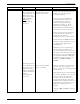
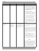
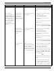
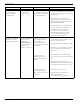


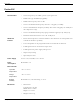

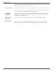
Table Of Contents
- 95 Series RFID System User’s Guide
- Table of Contents
- List of Figures
- Preface
- Introduction
- Reader R95 Installation and Connections
- Exciter E95 Installation and Connections
- Power Supply TRM95 Installation and Connection
- Configuration and Operation
- Before You Begin
- General Procedure Rules
- Setting Up the Reader/PC Connection
- Reader’s Power-up Sequence
- Learning Procedure (Optional)
- Resetting the Reader
- Checking the Reader’s Basic Parameters
- Setting Up the Exciter’s Address
- LF Transmitter Output
- Configuring the Reader
- Setting Up the Carrier Threshold
- Setting Up the Exciter’s Test-Tag
- Setting Up the Real Time Clock
- Configuring the Reader’s Application Parameters
- Configuring the Reader’s Network Parameters
- Storing the Reader’s Configuration
- Reader - Final Setup
- 95 Series RFID System - Final Test
- Programming and Testing the Transponder T95
- Troubleshooting
- Specifications
- Transponder T95 Messages
- Excitation Modes
- Reader Software Upgrade Procedure
- Glossary
- Index

General Guidelines
7-8 Troubleshooting
Excitation field
generated by the
Exciter is below
Specifications.
LF Transmitter
Output is low
(V
TAP
<80V
pp
).
The LF antenna loop has
a loose connection, or the
LF antenna is detuned
by a metallic object.
1. Check whether the LF antenna
wires are connected to the terminal
block (See LF Antenna Connections
on page 3-3).
2. Check the 3-wire connection
between the LF antenna terminal
block and the EXT95SC assembly
(terminal block TB2).
3. Check whether the recommended
setup guidelines for the Exciter’s
location are met. Pay special
attention to metallic surfaces
surrounding the Exciter, short-
circuit loops, and the spacing
between adjacent Exciters.
The Exciter responds
with C9 at the Self-
Diagnostic Procedure.
Exciter k responds
with C9 at the
command:
:TEST:EXCITER k
sent by the Main
PC (k is the
Exciter’s address).
A faulty Exciter or a
loose connection in the
power cable or
communication cable
between the Reader and
the Exciter.
A large magnetic
coupling between 2
adjacent Exciter E95
frames
The LF antenna is
detuned by metallic
objects that are in close
proximity.
1. Check the power cable and the
communication cable between the
Reader and the Exciter.
2. Check the Exciter’s address setting.
3. Check the LF Transmitter’s output.
(See LF Antenna Connections on
page 3-3).
1. Check the Exciter’s TAP voltage.
(See LF Transmitter Output on page
5-6).
2. Reposition the E95 frames to
minimize the unwanted modulation;
theamplitudeofV
TAPmin
>60V
pp
.
1. Check the Exciter’s V
TAP
.
2. Reposition the E95 frames to
minimize the detuning;
theamplitudeofV
TAP
>80V
pp
.
Problem Symptom Probable Cause Solution