
User's Manual
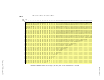
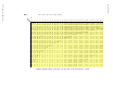


Table Of Contents
- 95 Series RFID System User’s Guide
- Table of Contents
- List of Figures
- Preface
- Introduction
- Reader R95 Installation and Connections
- Exciter E95 Installation and Connections
- Power Supply TRM95 Installation and Connection
- Configuration and Operation
- Before You Begin
- General Procedure Rules
- Setting Up the Reader/PC Connection
- Reader’s Power-up Sequence
- Learning Procedure (Optional)
- Resetting the Reader
- Checking the Reader’s Basic Parameters
- Setting Up the Exciter’s Address
- LF Transmitter Output
- Configuring the Reader
- Setting Up the Carrier Threshold
- Setting Up the Exciter’s Test-Tag
- Setting Up the Real Time Clock
- Configuring the Reader’s Application Parameters
- Configuring the Reader’s Network Parameters
- Storing the Reader’s Configuration
- Reader - Final Setup
- 95 Series RFID System - Final Test
- Programming and Testing the Transponder T95
- Troubleshooting
- Specifications
- Transponder T95 Messages
- Excitation Modes
- Reader Software Upgrade Procedure
- Glossary
- Index

Message Format
B-2 Transponder T95 Messages
The following is the method of evaluating the maximum transmission time for the
T95:
Number of bytes per message: TXBytes = SC + UD + CRC + Flag + Key
Number of bits per byte: BitsPerByte = 12 for DR4, and = 11 for DR3
Number of bits per message: TXBits = Sync + BitsPerByte*TXBytes
Bit duration: BitLen = 1/DR
Message length: MsLen = 0.0007 +TXBit*BitLen
Intermessage constant: InterMsgUnit = (UD + Flag)*0.0003066, for DR4;
= (UD + Flag)*0.0005657), for DR3
Intermessage delay: InterMsgDelay = [SD +RND(0…31)]*InterMsgUnit;
(RND - random value)
Maximum number of transmitted messages: NM = IP +RC; if LT = N
Total transmission time: TXTime = NM (MsLen +(NM-1) (InterMsgDelay)
Thefollowingtablespresentthemaximumnumberofmessages(NM)thatcanbe
transmitted in five seconds, using different sets of parameters for the T95.