
User's Manual
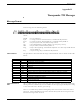
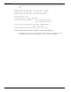
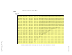
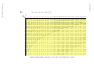


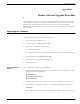
Table Of Contents
- 95 Series RFID System User’s Guide
- Table of Contents
- List of Figures
- Preface
- Introduction
- Reader R95 Installation and Connections
- Exciter E95 Installation and Connections
- Power Supply TRM95 Installation and Connection
- Configuration and Operation
- Before You Begin
- General Procedure Rules
- Setting Up the Reader/PC Connection
- Reader’s Power-up Sequence
- Learning Procedure (Optional)
- Resetting the Reader
- Checking the Reader’s Basic Parameters
- Setting Up the Exciter’s Address
- LF Transmitter Output
- Configuring the Reader
- Setting Up the Carrier Threshold
- Setting Up the Exciter’s Test-Tag
- Setting Up the Real Time Clock
- Configuring the Reader’s Application Parameters
- Configuring the Reader’s Network Parameters
- Storing the Reader’s Configuration
- Reader - Final Setup
- 95 Series RFID System - Final Test
- Programming and Testing the Transponder T95
- Troubleshooting
- Specifications
- Transponder T95 Messages
- Excitation Modes
- Reader Software Upgrade Procedure
- Glossary
- Index

Excitation Modes and Parameter Settings
Excitation Modes C-1
Appendix C
Excitation Modes
This appendix describes the various excitation modes (signal descriptions) and their
associated parameter settings.
Excitation Modes and Parameter Settings
The table below lists the excitation modes and the associated parameter settings.
Note (x)-canbeanything.
Excitation Mode [Signal Description] Parameter Settings
Continuous DC Mode (DC)
[Continuous Unmodulated Carrier (131.5kHz))]
RCS =N; RES=N; REM=C; RET=D; HCC=x;
HCS=x; HE1=x; HE0=x
Continuous AC Mode (AC)
[Continuous Carrier (131.5kHz), modulated ON/OFF by 610 Hz.]
RCS =N; RES=N; REM=C; RET=A; HCC=x;
HCS=x; HE1=x; HE0=x
Alternating Mode (ACDC)
[AC mode for 0.2s, followed by DC mode for 0.2s, and NO signal
for 0.1s. When a message is received, the existing excitation
type is extended for 0.5 s, and the cycle starts again.]
RCS =N; RES=N; REM=A; RET=x HCC=x;
HCS=x; HE1=x; HE0=x
Switching DC Mode (SMDC).
[Switching between DC mode for *10ms, and NO signal for
*10ms.]
RCS =N; RES=Y; REM=C; RET=D; HCC=x;
HCS=x; HE1= ; HE0=
Switching AC Mode (SMAC).
[Switching between AC mode for *10ms, and NO signal for
*10ms.]
RCS =N; RES=Y; REM=C; RET=A; HCC=x;
HCS=x; HE1= ; HE0=
Conditional Switching DC Mode (CSDC).
[When a valid message is received, the SMDC mode is modified
as follows: SMDC mode continues for *s, followed by DC mode
for *s, then back to the SMDC mode.]
RCS =Y; RES=Y; REM=C; RET=D; HCC= ;
HCS= ; HE1= ; HE0=
Conditional Switching AC Mode (CSAC).
[When a valid message is received, the SMAC mode is modified
as follows: SMAC mode continues for *s, followed by AC mode
for *s, then back to the SMAC mode.]
RCS =Y; RES=Y; REM=C; RET=A; HCC= ;
HCS= ; HE1= ; HE0=
Table C-1: Excitation Modes - Parameter Settings
α
β
αβ
α
β
αβ
γ
δ
δ
γαβ
γ
δ
δ
γαβ