
User's Manual


Connecting the Power Supply
3-6 Exciter EX21 Installation and Connections
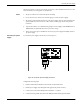
5. Switch on the power supply.
6. Check the voltage on the terminal block TB8 (between pins 1-3).
7. Plug terminal block TB8 into connector TB7.
8. Re-check the voltage in Step 6.
9. Check whether the voltage between pins 1 (Test) of J2 and Ground is 5.0 ± 0.2 V.
10. Switch off the power supply.
Note For this installation an isolation transformer is not required. However, if it is installed, the
equipment still can be used in a one Exciter per power supply configuration but it should be
connected as if it is a part of the multiple Exciters per power supply configuration (see Figure 3-4).
Multiple Exiters per
power supply.
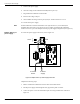
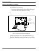
To connect the power supply to the Exciter, refer to Figure 3-4.
Figure 3-4: Multiple Exciters per Power Supply Connection.
Complete the following steps:
1. Remove terminal block TB8 from connector TB7 on the LFA21 board.
2. Run the power supply cable through the cable grip into the plastic enclosure.
3. Connect the power wires to the transformer input wires using terminal block as shown in
Figure 3-4.
Test
J2
J5J4
J1
1 2 3 4
S96
S21S95
L
O
L
O
TB8
~~
GND
22Vac
To Power
Supply
To another
Exciter