
User's Manual

Setting Up the Real Time Clock
Configuration and Operation 5-13
WRC=0 <Enter>
WRS=0 <Enter>
WSD=15 <Enter>
WSM=Y <Enter>
WTF=Y <Enter>
WTS=N <Enter>
WWP=Y <Enter>
WUD=$43FEnnrrkk <Enter>
where:
nn is the PC’s address. If PC’s address is 1, or there is only one PC/site, nn=01.
rr is the Reader’s address. If Reader’s address is 1, rr = 01.
kk is the Exciter’s address. If the Exciter’s address is 1, kk = 01.
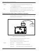
2. Turn off the LF field, by typing:
C<Enter>
3. Program the Exciter Test-Tag, by typing:
:TAG:MATCH:EXCITER k<Enter>
where k is the address of the Exciter you want to program.
If the response is not 00, the Exciter is not programmed. Repeat this command several times,
waiting at least 3 seconds between retries.
Note If you cannot program the Test Tag, see Chapter 7, Troubleshooting.
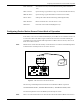
4. Turn on the LF field, by typing:
B<Enter>
5. Test the Exciter Test-Tag, by typing:
:TEST:EXCITER k<Enter>
where k is the address of the Exciter you want to test. The correct response is 00, followed by
a number of messages between IP-2 and IP. If less messages are received, verify whether the
UHF channel is jammed or replace the LFA21 board.
Note If you do not see the expected number of messages on your PC, (13-15 messages for an IPC site),
see Chapter 7, Troubleshooting and check the following parameters:
DAR=Y; DCI=0, DRI=0
6. Repeat Steps 1 to 5 for each Exciter that is connected to the Reader.
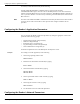
Setting Up the Real Time Clock
The Real Time Clock operation is controlled by the following commands/parameters: IUT, IUM,
DTS. For more information on setting up the Real Time Clock, refer to the RFID System S21
Reference Guide. You can set the Reader’s date and time by using the
IUT parameter.