
User's Manual


General Guidelines
Troubleshooting 7-7
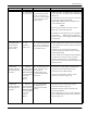
4.3. DATA LED
is not flickering
4.3.1. Exciter’s Test Tag is
placed beyond the limits
of the receiving zone, or
the noise level is too high,
or the Test Tag is out of
specifications.
1. Run the procedure, S21 RFID System - Final Test on
page 5-18. Step 2 - Set up the Carrier Threshold for
the Reader.
2. Check the RF level of the messages received from
the Test Tag; it must be higher than
(
RSS+HNL+3)dBm, that means 3dB above the
carrier threshold value.
Note
The Reader reports the RF level of the received
message only if the parameter
DLI=Y.
3. If the RF level of the Test Tag’s received messages
is lower than -85dBm, either reposition the
Reader or Exciter, or use a higher gain UHF antenna
for the Reader.
5. Excitation field
generated by the
Exciter is below
Specifications.
5.1. LF
Transmitter
Output is low.
5.1.1. The LF antenna loop
has a loose connection, or
the LF antenna is detuned
by a metallic object.
1. Check whether the LF antenna wires are connected
to the terminal block (See LF Antenna Connections
on page 3-3).
2. Check the 3-wire connection between the LF
antenna terminal block and the LFA21 assembly
(terminal block TB2).
3. Check whether the recommended setup guidelines
for the Exciter’s location are met. Pay special
attention to metallic surfaces surrounding the
Exciter, short-circuit loops, and the spacing between
adjacent Exciters.
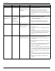
6. The Exciter
responds with CA at
the Self-Diagnostic
Procedure.
6.1. Exciter k
responds with CA
at the command:
:TEST:EXCITER
k sent by the Main
PC (k is the
Exciter’s
address).
6.1.1. A faulty Exciter or a
loose connection in the
power cable or
communication cable
between the Reader and
the Exciter.
1. Check the power cable and the communication
cable between the Reader and the Exciter.
2. Check the Exciter’s address setting.
3. Check the LF Transmitter’s output. (See LF
Antenna Connections on page 3-3).
7. The Exciter
responds with C9 at
the Self-Diagnostic
Procedure.
7.1. Exciter k
responds with C9
at the command:
:TEST:EXCITER
k sent by the Main
PC (k is the
Exciter’s
address).
7.1.1. A large magnetic
coupling between 2
adjacent Exciter EX21
frames
1. Check the Exciter’s TAP voltage. (See LF
Transmitter Output on page 5-8).
2. Reposition the EX21 frames to minimize the
unwanted modulation.
3. Only if absolutely necessary, consider readjusting
the C9 threshold (NVT). Refer to LF Transmitter
Output on page 5-8
Problem Symptom Probable Cause Solution