
User's Manual


Lyngsoe Systems Combi RFID Master MC30RG
Doc no. 950237 - Page 7 of 14
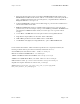
Figures 6 to 8 show a typical portal installation.
Figure 7 Figure 8
4. MC30RG Connections
Power Connection
WARNING! Before you start the installation, check if the Power Supply provides the specified output
voltage: + 24Vdc +/- 10%, and min. 5A for a portal in a fully equipped configuration. A universal power
adapter that accepts input voltages from 100V/1.2A to 240V/0.5A is recommended.
For the power connections use the 4.2mm Mini-Fit Jr receptacle (LS PN 350238) and the female crimp
terminals for AWG18-24 (LS PN 350238). Strip the wire isolation 3.0-3.5 mm and crimp the terminals on the
wire using the Molex crimping tool 11-01-0197. Insert the terminals in the receptacle body – terminals 1 for
(+24V), terminal 3 for (GND) voltage.
Remove the cover. Plug in the power connector into any of the corresponding headers J20 or J21 on the
MBD40 motherboard. The POWER LED (green) goes ON, and the display shows a “spinning wheel” pattern.
This pattern shows the portal is currently awaiting initialization commands from the PC and it will remain on
the display until a command is received by the motherboard to change it or a configurable timeout (default
5min, see parameter HPT) has elapsed. If no command was sent from the RS485 bus master (host PC) to
change the display prior to this timeout duration, the display will start to flash “FF” as a warning to the user
that communication with the host has not been established yet.
Wired Communication: RS485 Connections
For the RS485 connection use a standard Cat5 Ethernet cable and RJ45 plug. Crimp the connector using the
recommended tool and the following color scheme: pin 1 - Wh/Or; pin 2 – Or; pin 3 – Wh/Gr; pin 4 – Bl; pin
5 – Wh/Bl; pin 6 – Gr; pin 7 – Wh /Br; pin 8 – Br.
Insert the RS485 incoming cable in one of the J3 or J4 connectors, and the outgoing cable in the other one. The order
does not matter as the two connectors are connected in parallel. If the portal is an end unit, so if only one RS485 cable
is connected to the portal, move the J5 and the J6 jumpers to the “L” (loaded) position such that the line is properly
terminated.