
User's Manual


Lyngsoe Systems Combi RFID Master MC30RG
Doc no. 950237 - Page 8 of 14
5. Operation
5.1. The Display and the two buttons
The LS4230 portal includes a dual
digit display and two push buttons.
The display and the buttons are
visible as slave devices on the RS485
bus. Some command examples are
shown in chapter 5.4 “Remote
Control” and are described in more
details in the motherboard MBD40
Rev A user manual.
The two buttons are useful in
troubleshooting. After pressing one
of them, two events happen. Firstly,
status flags are updated in
motherboard’s RAM that can be read
remotely by querying the parameters
BTT and BTS. Secondly, the
“spinning wheel” sequence is shown
on the display to acknowledge the
press and signal that the portal is
waiting for the host to process the request. The “spinning wheel” sequence will also timeout after a specified interval
(default 30s, see parameter HBT) and then the display will flash “FF” again.
In a more powerful use scenario, the buttons and the display can be used to send test codes to the host computer. For
this, the MBD40 motherboard BCM parameter needs to be set first to a value higher than “0”. Then, by pressing the
“Test” button, an incrementing code from 0 up to the BCM value is displayed. When pressing on the “Send” button, the
displayed code is stored in the parameter “BCD”. This code, when retrieved by the host computer, can trigger different
actions like downloading remotely the data, or trigger different test programs. The specific actions are entirely
dependent on the host programming (EDECS). This feature may be useful during the entire life cycle from the
production process, installation and maintenance of the portals.
5.2. The Motion Sensor
The motion sensor is a Passive Infrared Receiver and responds to body heat so it tracks people’s movement. Its
sensitivity window has been adjusted to match the active reading area of the portal. It can be remotely enabled or
disabled by setting the EMS parameter.
5.3. The front panel LEDs
The portal also includes two LEDs. The GREEN LED labeled “Power” is ON all the time as long as the portal has
power. The RED LED labeled “Field” indicates the portal readiness to read active or passive tags. Its meaning depends
on the portal configuration and settings. There are three main scenarios.
A) In the simplest scenario, the Field LED is ON all the time and the LF Exciter and Passive Reader are ON all
the time, if equipped.
B) In the next scenario, the motion sensor is enabled. Whenever a motion is detected, the Field LED is turned ON
and an enabling signal is sent to the LF exciter and the Passive reader. They in turn start reading the active and
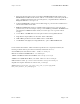
Figure 9
Cooling
fans and
vents
Status
LEDs
Two Push
Buttons
Display
Motion
S
ensor