LynTec RPC Instruction Bulletin Remote Power Controller Retain for future use.
HAZARD CATEGORIES AND SPECIAL SYMBOLS Read these instructions carefully and look at the equipment to become familiar with the device before trying to install, operate, service, or maintain it. The following special messages may appear throughout this bulletin or on the equipment to warn of potential hazards or to call attention to information that clarifies or simplifies a procedure.
RPC Controller Table of Contents Contents Chapter 1--Introduction....................................................................................................................................................................6 OVERVIEW .......................................................................................................................................................................................6 CONTENTS .............................................................................
RPC Controller Table of Contents Selecting breakers for Brownout or Emergency Shutdown............................................................................... 34 Brownout Thresholds ....................................................................................................................................................... 34 Schedule Setup.........................................................................................................................................................
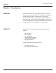
Chapter One--Overview Introduction Chapter 1--Introduction OVERVIEW This bulletin explains how to install and operate the LynTec Remote Power Controller (RPC). The controller uses remotely operated circuit breakers to control up to 167 remotely operated branch circuits. Control signals originate externally from commands received via the communications network or from dry contact inputs. Acceptable communications protocols include TCP/IP, RS-232, and DMX-512. RS-485 optional.
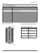
Chapter One--Overview Controller Overview Controller overview Figure 1–1 shows the parts of the RPC controller. A brief description of each part follows in Table 1–1. Figure 1-1: RPC Controller D A. B. C. D. E. F. G. H. I. J. K. L. M. N. O. P. Q. R. S. T. U. V. W. X. Y. Z.
Chapter One--Overview Controller Overview Table 1-1: Parts of the RPC Controller Component Description N. Reset Button Resets the controller. O. MPE Port Connects the Multi Panel Expander Board (for use with up to 3 slave panels) P. I/O Board Port Connects additional I/O boards to the controller. Up to two boards can be added for a total of 38 contact closure inputs. Q. Power Led Illuminates when the controller is receiving power. R.
Chapter One--Overview Additional Boards Overview Figure 1-3: Multi-Panel Expander Board Figure 1–3 shows the parts of the additional slave board. A brief description of each part follows in Table 1–3. E A F B G C D Table 1-3: Parts of the Multi-Panel Expander Board 8 Component Description A. Power LED The power LED is always orange when the board is receiving power. B. Power Input Provides power to control busses on panels two, three and four. C.
Chapter Two--Safety Precautions Chapter Two--Safety Precautions This chapter contains important safety precautions that must be followed before attempting to install, service, or maintain electrical equipment. Carefully read and follow the safety precautions below. ! DANGER HAZARD OF ELECTRIC SHOCK, EXPLOSION, OR ARC FLASH This equipment must be installed and serviced only by qualified electrical personnel.
Chapter Three--Quick Start Guide Chapter Three--Quick Start Guide INTRODUCTION This chapter is a quick reference listing the steps necessary to install the RPC system. The steps in this chapter are provided as an installation checklist. For complete installation instructions, refer the chapter listed. Steps 1. Install all the RPC components according to their instruction bulletins.
Chapter Four--Wiring Chapter 4--Wiring To initially wire the RPC follow these easy steps: 1. Install and connect all main and neutral feeds as per NEC. 2. Install and connect the Isolated Technical Ground feed from the star ground of the isolation transformer or the tie point from a ground rod or building steel to the Isolated Technical Ground bar in the ITG sidecar. 3.
Chapter Four--Wiring 6. Connect the green 14 AWG wire from the ground terminal of the Power Supply unit to the ground bar attached directly to the panel interior (DO NOT attach to the isolated technical ground in the sidecar). 7. Install and connect all load, neutral and Isolated Technical Ground feeds to circuits. 8. Ensure that all bolts and lug connections in the panel are tight. Check both sides of the main breaker, the bars connecting the busses to the main and all breaker retaining bolts. 9.
Chapter Four--Wiring 2. At the RPS Slave panels, strip the cable sheath back approximately 20 inches. Cut the conductors for Left Bus B, Left Bus A, – and + down to approximately 4 inches and terminate them in the Left Bus screw-terminal header from left to right. Terminate the remaining two conductors in the Right Bus B and Right Bus A positions of the Right Bus screw-terminal header. 3. Using two cut lengths of 18 AWG wire, install jumpers from Left Bus – and + to Right Bus – and +.
Chapter Four--Wiring Figure 4-3: Digital I/O Remote Switch and Sensor Wiring RJ-25 6P6C Flat Cable to I/O Port on Controller 24 VDC LED Indicator I/O Port OUT 24V IN 1 2 10 3 11 4 12 5 13 6 14 7 15 8 Momentary ON Contact Switch Momentary OFF Contact Switch 9 24 VDC LED Indicator Maintained Contact Switch Light Sensor for Zone Control 16 I/O Port RJ-25 6P6C Flat Cable to next I/O Board Switches or sensors being used to control either sequenced or grouped zones are to be connected to t
Chapter Four--Wiring Audio Sensing Timer (AST) Wiring: One (1) Audio Input three-position spring-terminal header (located on the right side of the Controller board) is provided for the Audio Sensing Timer function. Connect to a balanced audio line with the input+, common and input– terminated from top to bottom in the header. The voltage threshold for this input is set using the adjacent potentiometer. The trigger point for the AST function is established during Panel Setup.
Chapter Four--Wiring Emergency Shutdown Wiring: To connect your fire alarm or emergency management system to the RPC, follow these steps. 1. From the fire alarm unit or latching Emergency Shutoff switch, wire the Normally Open (NO) contacts to the IN and 24V positions of Digital I/O Port #1 on the Controller. 2. If a remote status indicator is used, ensure that the positive terminal is wired to the 24V position and the negative terminal is wired to the OUT position of Digital I/O Port #1. 3.
Chapter Four--Wiring Figure 4-5: Control Wiring Ethernet Cable to Facility Network 24 VDC LED Indicator Momentary ON Contact Switch Momentary OFF c – + Input Thru DMX-512 Control Digital I/O 1 c – + Ethernet Cat 5e RX RS-232 1 2 24 VDC LED Indicator Maintained Contact Switch Analog Inputs for Control Functions TX Analog Inputs IN 24V OUT 2 3 3 + 4 Audio Sensing Timer c – Light Sensor for Zone Control OFF ON 5 I/O 6 Left Bus Right Bus MPE + – 24VDC source for external devic
Chapter Four--Wiring Switch Wiring Instructions The I/O ports on your RPC controller allow for a variety of switch options. LynTec SS-2 Switch Set Using a standard LynTec SS-2 Switch Set with illuminated ON switch. See Figure 4-6 1. Wire the ON switch to Digital I/O port 2 on the left edge of the Controller board as follows: i. Connect the 24VDC Common (center terminal of the I/O port) to the C pin of the ON switch. Jumper the C pin of the ON switch to the + pin. ii.
Chapter Four--Wiring SS-2PL and SS-2LRP Locking Switch Sets Using a standard LynTec SS-2PL or SS-2 LRP Switch Set with illuminated ON switch. See Figure 4-7 1. Wire the ON switch to Digital I/O port 2 on the left edge of the Controller board as follows: i. Connect the 24VDC Common (center terminal of the I/O port) to the + pin of the ON switch. ii. Connect the + pin on the on switch to the 1 pin on the lock. iii. Connect the Input terminal (arrow pointing towards header) to the NO pin of the ON switch.
Chapter Four--Wiring Figure 4-10: Complete RPC Wiring DMX-512 Input RS-232 Input LAN Slave Panels S2 S3 PWR M S4 Control IN I/O OUT DMX-512 Cat 5e RS-232 1 Analog 1 2 2 C 3 4 5 3 A S T L Bus R Bus PWR I/O MPE 24V 6 Control Bus I/O I/O 1 9 1 9 2 10 2 10 3 11 3 11 12 4 13 5 6 14 6 14 7 15 7 15 8 16 8 4 5 E I/O E 12 13 16 I/O ++ –– --++ 1 2 OUT B T P IN 3 4 NL Controller Power Breaker 20 139-0498-0120
Chapter Four--Wiring Figure 4-11: RPC Mechanical Drawing 28.00" 2.00" 8.50" 15.00" High voltage interior may be field inverted for top feed Breaker Control Busses Multi-Panel Expander Board Master Controller Optional - Digital I/O Expander Boards Low Voltage Cabinet 56.00" Power Supply, Buffer and VoltageTransducer 1.5" I.D. wiring access nipples between sidecars and panelboard Feed 2/0 max. 50.00" Isolated Technical Ground Bar 46 positions 14 - 4 ga. Feed 4/0 max.
Chapter Four--Wiring INITIAL POWER UP PROCEDURE With panel door open and breakers visible, turn on the panel main breaker and the Controller Power 15 Amp circuit breaker. The green ‘DC OK’ LED should illuminate on the Power Supply and the green ‘STATUS’ LED on the Buffer unit should begin flashing steadily. The Buffer ‘STATUS’ LED will be constantly lit when the unit has been fully charged. The Controller LCD display and orange Power LED should illuminate.
Chapter Five--Control Setup Chapter 5--Control Setup (Web Page) OVERVIEW STATUS There are 4 main tabs on your RPC web page. This page will give you a quick overview of the pages and their functions. The status page allows you to view the current status of the breakers and zones. Zones and individual breakers cannot be manipulated from this page. CONTROL This page allows the user to manipulate individual breakers as well as breaker zones.
Chapter Five--Control Setup Setup SETUP HOME This section will guide you through the process of setting up yur RPC Controller. First enter the IP address or NetBios name into your web browser. When the RPC screen pulls up. Select “Setup” and “SetupHome” Tabs. Figure 5-1--Setup Home To set the username and password for your panel, click the Setup tab. The Setup Home tab should be displayed. The default username displayed should be “admin” and the password fields should be “pw”.
Chapter Five--Control Setup Basic date and time information will be displayed in the Clock Set fields. Verify that the year, month and day are correct. Set the hour to the appropriate time for your time zone and verify that the minute displayed is correct. Save this information by clicking the Update Information button below the Clock Set portion of the window. Click the radio buttons for any pages to be printed out under the Printable Pages header.
Chapter Five--Control Setup Figure 5-3: Interface options NetBios Name The NetBios name defaults to LynTecRPC. Each master panel in your system should be assigned a unique NetBios name. After names are assigned the user can access the system web page by entering the NetBios name into the web browser instead of using the IP address. Port Type The port type section is used to select the preferred serial communication protocol.
Chapter Five--Control Setup Panel Setup This section explains how to setup your panel and motorized breakers for remote operation. BREAKER SETUP To setup breakers, follow these steps: 1. Under Setup, go to the Panels tab. 2. After breakers are installed by a qualified electrician, click the “Scan Breakers” button. Motorized breakers are represented in white, unmotorized breakers or blank spaces are represented in gray. Figure 5-4 3.
Chapter Five--Control Setup 4. Assign names to the breakers. (Figure 5-5) Figure 5-5 ZONE SETUP Breakers can be controlled individually or arranged into zones. Breakers in zones can be toggled at 25 ms intervals (Grouped Operation) or at variable intervals (Sequenced Operation). To setup a Zone follow these steps: 1. Choose which zone you would like to edit. (Figure 5-6) Figure 5-6 Select to Edit 28 139-0498-01.
Chapter Five--Control Setup 2. Name the Zone. (Figure 5-7) 3. Choose Grouped or Sequenced operation. (Figure 5-7) Figure 5-7 Name the Zone Choose grouped or sequenced from the dropdown 5. Select a breaker to add to the zone by clicking on the breaker you want to add. Only motorized breakers (indicated in green) may be added to zones. (Figure 5-8) Scroll down to add breakers from additional panels. Figure 5-8 Click on the green oval to add a breaker to a zone. 6.
Chapter Five--Control Setup Figure 5-9 Click the up/down arrows to change the breaker’s position in the zone. Select a delay time for the breaker. 8. Click the “Close” button when finished to save. OR, click “Remove” to remove the breaker from the zone. 9. When finished adding breakers to the zone, click the “Test Mode” (Figure 5-10) button to do a blind test (breakers will not actually toggle). Please note that delay times larger than one second are reduced to one second in Test Mode for expediency.
Chapter Five--Control Setup Figure 5-11 GLOBAL PREFERENCES SETUP This section guides you through the setup process for the many features and preferences in your RPC system. Labeling In addition to labeling breakers, each panel in your RPC system can be named (up to 16 characters) and the changes dated (Figure 5-12). For multi-panel systems, scroll down to see additional panels.
Chapter Five--Control Setup Global Control Preferences The following features can be selected for additional system flexibility Figure 5-13 Table 5-1 All On/Off Hurry-Off Emergency Shutoff Audio Brownout 32 Turns all the breakers on or off by order of zone and sequence. Manually turns breakers off. Turns Selected breakers off when the fire alarm or emergency management system engages. Must be connected to I/O position one. Activates the optional audio sensing timer.
Chapter Five--Control Setup Selecting breakers for Brownout or Emergency Shutdown Figure 5-14 Select breakers to actuate in the event of a brownout in green outlined check boxes. Select breakers for emergency shutdown in pink outlined check boxes. Select breakers to actuate in the event of a brownout by checking the green box next to the breaker. Select breakers to turn off in the event of a fire or other emergency by checking the pink box next to the breaker.
Chapter Five--Control Setup Schedule Setup Follow these steps to set a schedule. 1. Rename each schedule as desired 2. Assign weekday (M-F) on and off times by clicking on time and off time buttons, using pull-down menu and clicking the pick button to select. 3. Assign weekend (S-S) on and off times by clicking on time and off time buttons, using pull-down menu and clicking the pick button to select. 4. Enable each schedule by clicking the checkbox for that line. 5.
Chapter Five--Control Setup Contact Closure Setup Configure the digital I/O port and link it to a zone as follows: Note: If the Emergency Shutoff feature is selected, the first position in the Onboard field (on the Controller) is automatically assigned to that. 1. Rename each contact closure as desired 2. Select contact closure action type 3. Use CC Module 1 and CC Module 2 only if I/O Expander boards are installed. 4.
Chapter Five--Control Setup Individual Momentary Contact ON and Using a standard LynTec SS-2 Switch Set with illuminated ON OFF Pushbuttons switch or two illuminated pushbuttons: Configure the Digital I/O port and link it to a zone as follows: 1. Follow the previous instructions for naming the contact closure and setting closure type. 2. Click the M button at the right side of the first of the two ports used.
Chapter Six--Operation Chapter Six: Operating your RPC Figure 6-1 Using the built-in web page To operate the RPC using the built in web page, select the control tab from the top of the page. Once on the CONTROL page, simply click each breaker for individual control. Or, click a zone for zone control. “All zones ON” and “Hurry-Off ” commands can also be executed from this page.
Appendix A Appendix A--RPC Quick Start Guides RPC to RPS Wiring Instructions Figure A-1 Left Bus B Left Bus A Right Bus B Right Bus A Twisted Pair Twisted Pair Slave Common Slave +24VDC Slave Panel 2 Power B A + Slave Panel 3 Slave Panel 4 Controls Communication Power Slave address selector Master Panel Slave Panel 2 38 Slave Panel 3 Slave Panel 4 139-0498-01.
Appendix A 1. If RPS Slave panels are being used in conjunction with an RPC Master panel, install and connect one 18 AWG six (6) conductor (Belden 27600 A or equivalent) or two 18-24 AWG twisted pairs for data and one 16-18 AWG for power per RPS unit. Terminate the Left Bus B, Left Bus A, Right Bus B, Right Bus A, Common (–) and 24VDC (+) in the screw-terminal header for that RPS (Slave Panel 2 – 4) from left to right. 2. At the RPS Slave panels, strip the cable sheath back approximately 20 inches.
Transducer Neutral Transducer Load Power Supply DC + Power Supply DC – N L ++–– Panel Neutral Bus 15A Breaker Panel Ground Bar Controller Cable Controller Cable 2 Confirm that the electrician has connected the 15A breaker in the master panel (position 21) to the power supply in the lower sidecar. Confirm that RPS (slave) panels are connected to the master as indicated in the “RPC to RPS Wiring Instructions” bulletin.
139-0498-01.41 6 Complete the RPC setup by following the steps in Chapter 5. If desired, set your username and password on the “Setup Home” page under the “Setup” tab. The default username is “admin” and the initial password is “pw”. 5 Open a web browser and access the status page via the IP address of the RPC. (ex. http://192.168.1.
Confirm that RPS (slave) panels are properly connected to the master as indicated in the “RPC to RPS Wiring Instructions” bulletin. 2 Complete all the steps in the “RPC Quick Start Guide”. 1 Using a standard LynTec SS-2 Switch Set with illuminated ON switch. (For other types of switches, consult CH 4 of the instruction bulletin for wiring diagrams.) Contact Closure Wiring Instructions RPC LynTec B. Connect the Input terminal to the NO pin of the OFF switch A.
139-0498-01.43 D. Click the “Save Changes” button at the top of the Onboard I/O box. C. Ensure that both of the Action selections for both ports are set to Momentary NO. B. Click the M (merge) button at the right side of the first of the two ports used. The name box and M button in the second port should turn gray and the Action selections should default to Momentary NO. (normally open) A.
Appendix B Appendix B--RS-232 and TCP/IP Protocols RS-232 PROTOCOL Table B-1 Command Codes Addressing Scheme Command Decimal Hexidecimal Start Byte Activate breakers Deactivate breakers Request all breakers status Activate zones Deactivate zones Request zones status Event ON Event OFF Event status Request breakers status Request bus status Breaker status identifier Zone status identifier Event status identifier Emergency override identifier Checksum identifier Checksum digits Stop byte 176 180 181 183
Appendix B Deactivate breakers 0xB0, 0xB5, breaker_address_1, …, breaker_address_n, 0xF0 breaker_address_1, …, breaker_address_n – addresses of reakers to be deactivated n<=168 Activate/deactivate breakers 0xB0, 0XB5, breaker_address_1, …, breaker_address_m, 0xB6, breaker_address_1, …, breaker_address_n, 0xF0 breaker_address_1, …, breaker_address_m – addresses of breakers to be activated breaker_address_1, …, breaker_ address_n – addresses of breakers to be deactivated m+n<=168 Request all breakers status
Appendix B Reply to request breakers status command: Same format as “Request Bus Status”; contains addresses and status of the breakers specified in the request command Reply to request all breakers status command: status of all breakers 0xB0, 0xB6, byte_1, …, byte_84, 0xF0 byte_i: bits 7-4: status of breaker # 2i, bits 3-0: status of breaker # 2i-1, i=1-84 Reply to request bus status command: status of all breakers of the requested bus 0xB0, 0xBE, byte_1, …, byte_11, 0xF0 byte_i format is identical to 3.
Appendix B Reply to activate/deactivate zone command: status of updated zones 0xB0, 0xC9, zone_address_i, zone_status_i, zone_address_j, zone_ status_j, …, zone_address_n, zone_status_n, 0xF0 zone_address_i, zone_status_i, zone_address_j, zone_status_j, …, zone_address_n, zone_status_n – addresses and status of zones updated by the command reply is generated for Reply to request zone status command: status of all 12 zones 0x40, 0xB9, byte_1, byte_2, byte_3, 0x80 byte_i: bits 7-6: status of zone # 4i, bits
Appendix B Request event status 0xB0, 0xBC, 0xF0 Reply to activate/deactivate event command: status of updated events 0xB0, 0xCA, event_address_i, event_status_i, < event_address_j, event_status_j>, 0xF0 event_address_i, event_status_i, < event_address_j, event_ status_j>– addresses and status of events updated by the command reply is generated for Reply to request event status command: status of all 2 events 0xB0, 0xBC, status_byte, 0xF0 status_byte: bits 3-2: status of event #2, bits 1-0: status of event
Appendix B Checksum Checksum is optional. It is calculated as a sum of all bytes of the message starting with start byte and ending with checksum identifier. Checksum is transmitted as a sequence of 3 bytes, where 1st byte is (hundreds+0xCD), 2nd byte is (tens+0xCD) and 3rd byte is (units+0xCD). For example, checksum=137 will be transmitted as: 0xCE, 0xD0, 0xD4 TCP/IP PROTOCOL Notice: Lyntec RPC firmware version 1.18a or later is required to implement this scheme.
Appendix B Events Control = E GET /p2.rpc?IPE001=1 This control string will turn event #1 on. GET /p2.rpc?IPE001=0 This control string will turn event #1 off. Events include: Event 1 = “All Breakers ON” Event 2 = “All Breakers OFF” Event 3 = “Hurry OFF” zips all breakers off fast.
Appendix C--Troubleshooting/FAQ Appendix C--Troubleshooting TROUBLESHOOTING THE CONTROLLER Use the following table if you need to troubleshoot the RPC controller. ! DANGER HAZARD OF ELECTRIC SHOCK, EXPLOSION, OR ARC FLASH • This equipment must be installed and serviced only by qualified electrical personnel. • Apply appropriate personal protective equipment (PPE) and follow safe electrical work practices. See NFPA 70E.
Appendix C--Troubleshooting/FAQ Table C-1: RPC Controller Troubleshooting Condition Controller LEDs and status indicators do not illuminate. Motorized circuit breaker does not respond to input change or does not respond as desired. 52 Possible Causes Solutions Power supply is not energized. Verify that the power supply’s LED status indicators are ON. Make sure the 15A breaker that provides power to the power supply is on. Also, verify that the power supply line terminal is secured.
Appendix D Appendix D--RPC System Components The LynTec system consists of control buses, a panelboard, remotely operated circuit breakers, a power supply, a buffer, a transducer and a controller. Optional expansion boards are available to add up to three additional panels or 16 or 32 additional I/o outputs. Figure B–1 identifies main components which are described in this appendix.
Appendix D Control Bus The control buses provide control and data monitoring for remotely operated circuit breakers and are connected to the power supply and controller. Installed control buses will not interfere with the installation of standard circuit breakers into the panelboard.
Appendix D Power Supply The Power Supply connects to a 15A non-motorized breaker and provides 24VDC, 3A power to the RPC controller. Figure D-4 Buffer The buffer stores DC power and discharges it during a brownout or power loss condition to turn off selected breakers (up to four panels). This is a capacitive buffer and is lead and acid free. Figure D-5 Transducer The transducer converts incoming AC line voltage to a varying DC output, allowing the RPC to monitor line voltage.
Appendix D Controller The RPC Controller provides control logic for the operation of a RPC system. The controller uses remotely operated circuit breakers to control up to 167 remotely operated branch circuits. The built in web server allows for easy setup and operation. Also, it provides input channels for connecting external dry-contact control devices. Figure D-7 Slave Address Selector The slave address selector is used to set an address for a control bus on a slave panelboard.
Appendix D Inputs Six (6) independently configurable digital inputs/outputs Input Types Maintained N.O. Maintained N.C. Momentary N.O. Momentary N.C.