
User Manual

Using the AES16e
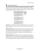
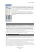
With Dual Wire Out enabled, the AES16e translates output signals to dual-wire connections according to
the second table. In this mode, output channels 5 – 8 are not active.
Input Connector Mixer Input Channel
IN 1 Digital In 1L
IN 2 Digital In 1R
IN 3 Digital In 2L
IN 4 Digital In 2R
IN 5 Digital In 3L
IN 6 Digital In 3R
IN 7 Digital In 4L
IN 8 Digital In 4R
Dual-wire Input Routing
Mixer Output
Channel
Input Connector
Digital Out 1L OUT 1
Digital Out 1R OUT 2
Digital Out 2L OUT 3
Digital Out 2R OUT 4
Digital Out 3L OUT 5
Digital Out 3R OUT 6
Digital Out 4L OUT 7
Digital Out 4R OUT 8
Dual-wire Output Routing
7.6 ASIO Specific Setup (Windows only)
Several control parameters of the AES16e are accessible from the ASIO Control Panel within applications
that utilize the AES16e ASIO driver. One of the benefits offered by this inter-application control, is that
these parameters can be saved with a project – allowing consistent performance conditions each time a
project is opened.
For this reason, it is preferable to initiate these settings from within the ASIO application, rather than from
the Lynx Mixer Adapter window whenever possible. All ASIO Control Panel settings except for Buffer
Size are application specific, so if more than one ASIO application is used, the settings will be need to be
established as appropriate for each application.
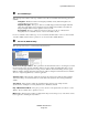
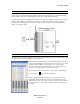
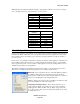
The ASIO Control Panel can generally be launched from the settings or options menu where the active
ASIO device is established. The following parameters are accessible from this window:
Buffer Size - This control allows the size of the ASIO buffer in samples to
be established. The buffer size is the primary factor in the amount of
latency that a user will experience when using the AES16e. For details, see
Section 7.8 Controlling latency by changing buffer size.
Latency – Displays the amount of latency in milliseconds that is the result
of the selected buffer size at the active sample rate.
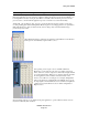
Unique Input and Output Names – These switches allow the user to
select if "Left" & "Right" are appended to the device names within the
ASIO application. When checked, "Left" & "Right" are appended to the
device names such as "Record 1 Left". When unchecked the device names
are simply "Record 1".
AES16e User Manual
Page 60