
User Manual

Configuring Multiple AES16e’s
Open the Adapter page for the card that is functioning as the clock master. Make sure that the
PREFERRED CLOCK SOURCE for this card is set to “Internal”. For the first clock slave card, open its
Adapter window and verify that a sample rate is displayed next to “Header” in the PREFERRED CLOCK
SOURCE section. If not, power down the computer, check cable connections and card orientation, and then
power up and check again. If a sample rate is displayed next to “Header”, then select “Header” as the
preferred clock source. If no audio applications are open, “Header” should then become the “Current
Source” at the top of the Adapter page. Repeat this process for every slave card in the system.
9.1.2 All Lynx cards as clock slaves
If your studio is oriented around a dedicated clock source, or you prefer to have your AD/DA converters
operate as clock masters, the Lynx cards in your system can be configured to slave to an external clock
reference.
Clock can be received by the AES16e cards via word-clock connections when the CBL-AES1604 cable
sets are used - see (section 3.3.1 External Clocking) or by slaving to the signals presented to the digital
inputs. When multiple digital devices are connected to the Lynx cards it is essential that all of those devices
are synchronized to a single clock source for proper operation. It is generally recommended to avoid “daisy
chaining” clock connections between digital devices beyond a second generation as the clock signal can
degrade. In such cases it is preferable to use some form of clock generation to insure the word-clock
integrity.
After the cable connections have been established, the clock sources for each card must be set correctly in
the Lynx Mixer. One at a time, open the Adapter page for each card in the system. Verify that a sample rate
is reported next to the target clock source in the “Preferred Clock Source” section of the Adapter page. For
the word-clock input, “External” would be the appropriate choice. For a digital input, “Digital In 1-4”
would be appropriate. If no sample rate is present, verify cable connections and check again. When a
sample rate is reported as expected, select the appropriate source as the “Preferred Clock Source”. If no
audio applications are open, the selected source should then become the “Current Source” at the top of the
Adapter page. Repeat this process for every card in the system.
The AES16 and AES16e feature the Lynx SynchroLock technology (see SynchroLock) which regenerates
clock signals on output. For this reason, it is perfectly acceptable to daisy chain clock signals between
Aes16 and AES16e cards without concern for clock degradation. Therefore, one legitimate clock
configuration is to provide a clock signal to one Lynx card in a multi-card configuration through a word-
clock or digital input connection, and then daisy chain the clock signal from that Lynx card to the others in
the system. The Word-clock “daisy-chain” can be connected internally using the CBL-ICC Internal Clock
Cable, which is available from Lynx. The CLOCK OUT header of one card is connected to the CLOCK IN
header of the next card. A separate cable is required for each slave card in the system. See Clocking
multiple cards with the CBL-ICC Internal Clock Cable. Alternatively, the CLOCK connectors on the CBL-
AES1604 cables can be connected externally with a standard 75 ohm BNC patch cable.
In this case, the card receiving an external clock signal should be set to “External” (for a word-clock
connection) or “Digital In 1-4” (for a digital input connection) as the Preferred Clock Source in the Lynx
Mixer Adapter page. The other cards should be set to “Header” if the CBL-ICC clock cable is used, or
“External” if a word-clock patch cable is used for the clock connections.
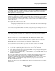
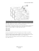
9.1.3 Clocking multiple cards with the CBL-ICC Internal Clock Cable
Starting with the master AES16e, insert the plug on one end of a Lynx Internal Clock Cable into the
CLOCK OUT header, until it clicks and locks into place. This header is polarized to ensure the correct
orientation of the cable plug. Insert the plug on the free end of the cable into the CLOCK IN header, on the
nearest slave AES16e. Connect each slave in a similar manner. Refer to the figure below:
AES16e User Manual
Page 65