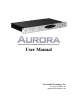
Mastering Analog to Digital and Digital to Analog Converter User Manual Lynx Studio Technology, Inc. www.lynxstudio.com support@lynxstudio.
User Manual Table of Contents 1 Introduction .......................................................................................................... 1 1.1 1.2 1.3 1.4 1.5 1.6 1.7 Overview ...................................................................................................................... 1 Features ........................................................................................................................ 2 Nomenclature used in this manual .................................
1 Introduction Thank you for choosing the Lynx Aurora 8™ / Aurora 16™ mastering AD/DA converter. The Aurora has been designed to provide you with the highest quality professional audio performance available, offering unequalled Analog-to-Digital and Digital-to-Analog conversion, flexible routing capabilities, I/O expansion options, external control functionality, and maximum channel capacity within a spaceefficient, single rack-space chassis. Please take a few moments to read through the entire user manual.
operation of the unit. The Aurora firmware can be programmed via a connected Lynx audio interface, infrared or MIDI. 1.2 Features 16-channels of Analog-to-Digital and Digital-to-Analog conversion. Aurora 8 8 -channels Support for 44.1, 48, 88.2, 96, 176.4 and 192kHz sample rates. Sturdy, road-worthy, single rack-space chassis. 16-channels of AES/EBU digital I/O in Single-Wire mode, 8-channels in Dual-Wire mode. Aurora 8 8-channels in Single-Wire mode, 4-channels in Dual-Wire mode.
1.4 In the Box The following items are included in your Aurora carton: Aurora Rack-Mount Converter AC Power Cord Aurora QuickStart Guide Aurora User’s Manual Warranty registration card If any items are missing or damaged, please contact your dealer or Lynx at http://www.lynxstudio.com. 1.5 Power and Safety Information To prevent fire or shock hazard, do not expose this equipment to rain or moisture. Do not block any of the ventilation openings.
are capable of delivering +20 dBu signal levels, it is important to verify that connected equipment is capable of handling these signal levels to prevent clipping or possible damage. 1.7.2 Remote Control In addition to front panel controls, the Aurora can be configured conveniently from the Aurora Remote Control software installed on a PC or Macintosh computer. A forthcoming Remote Control manual will detail the software installation and operation.
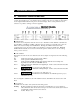
2 Operational Overview 2.1 Front Panel Controls and Indicators The Aurora allows extensive parameter selection and configuration from convenient front panel controls. For standalone use, or in situations where computer control is not possible, it is important to be thoroughly familiar with the front panel controls and display. If the correct parameters are not selected, it is possible to damage connected equipment.
No LED SynchroLock is disabled by remote control or the source is outside of SynchroLock range and the Aurora has reverted back to the wide-range analog PLL. If SynchroLock failed to lock, you can tap through the SYNC SOURCE options to return to the original source to re-engage the SynchroLock clocking system. r TO ANALOG OUT This button selects the signal source that will be routed to the analog outputs. This is a global selection, affecting all analog channels.
o METER This button determines whether the peak meters display input activity for the digital or analog inputs. This button also determines the behavior of the TRIM/AES MODE controls. When the ANALOG LED is ON the meters indicate the levels for the analog inputs and outputs and the TRIM/AES MODE button controls the TRIM. When the DIGITAL LED is ON the meters indicate the levels for the digital inputs and outputs and the TRIM/AES MODE button controls the AES MODE.
become operational. In ON mode, when AC power is applied the Aurora will be ready to use. ON is the ideal setting when a single power switch is used to turn on an equipment rack. To activate, hold the POWER button while connecting AC power. PLEASE NOTE: After the mode is changed the unit must be put into standby mode to save this setting before power is removed again. This function requires firmware revision 11 or higher in order to operate.
k AES I/O 1-8 (PORT A) 25-pin D-Sub connector provides access to AES/EBU Digital Inputs and Outputs 1-8. Please refer to Section 2.4 Cable Connections for more information about compatible cable sets. l LSLOT EXPANSION PORT Port for installation of LSlot or LStream expansion cards, used for expanding Aurora's interface options. Currently, the LT-ADAT expansion card is available to provide ADAT Lightpipe I/O. Other formats will be available soon.
2.4 Cable Connections Compatible cables for the Aurora analog and digital I/O ports are available directly through Lynx. The 25-pin D-Sub connectors on Aurora conform to industry-standard pin configurations, so that off-theshelf cable solutions are available from third party suppliers should custom lengths or connector types be required.
2.6 Clock Settings and Connections In any system with more than one digital device, there can be only one master clock providing synchronization to all connected devices. Whether you designate the Aurora as the clock master, thereby slaving all other devices to the Aurora, or slave the Aurora to another clock master, it is important that only a single device act as clock master, to prevent the occurrence of audible digital errors.
2.6.2 Aurora as Clock Slave The Aurora can synchronize to sample clock from a variety of external sources. In order to establish the Aurora as a clock slave, the correct clock source must be specified and the appropriate physical connection made. A two-stage phase-lock loop system is used to generate a high-frequency PLL clock while attenuating jitter in the selected sample clock source. Refer to Section 2.6.3 for a description of the operation of the PLL’s.
2.6.3 SynchroLock The Aurora incorporates SynchroLock clock synchronization technology to provide extreme tolerance to noisy external AES/EBU and word clock signals while generating an ultra-low jitter clock. This technology is especially useful for combating noise induced on cables in complex studio installations. SynchroLock provides clock synchronization while insuring bit-perfect digital transmission.
3 Common Studio Setups The Aurora has been designed to operate effectively in a variety of audio production contexts. The purpose of this section is to illustrate some possible studio setups for these contexts. 3.1 Aurora 16 as front end of digital mixer The illustration below details the connection of the Aurora 16 to a digital mixer, providing 16 channels of AD and DA conversion.
3.1.1 Clock settings To use the Aurora as the clock master, select “INT” as the SYNC SOURCE from the Aurora front panel. Also, select the appropriate sample rate for your project. Make sure and only choose sample rates supported by your mixer. Change the clock source setting of the digital mixer to slave to one of its digital inputs. 3.1.2 Routing In this instance, signals from the analog inputs should be routed to the digital outputs for delivery to mixer channels.
3.2 Aurora 16 in computer recording system with AES16 This configuration facilitates 16 channels of Analog input and output to a computer installed with a Lynx AES16 AES/EBU Interface. The routing features of the Aurora 16 are augmented by the latency-free monitoring and routing features of the AES16, and external control is possible with the external remote control software. Communication between the AES16 and Aurora 16 occurs via two CBL-AES1605 cables, each of which transmits 8 channels of AES I/O.
3.2.1 Clock settings Clock settings should be established from the Lynx Mixer and the Aurora front panel. The Aurora should be SYNC SOURCE set to “AES A”. When a sample rate is chosen from the AES 16 Adapter page, or when playback or recording is initiated from a software application, the corresponding SAMPLE RATE LED on the Aurora front panel will illuminate. The AES16 should be set to “Internal” in the AES16 Adapter page. 3.2.
3.3 Aurora 8 in Computer System with LynxTWO/L22 This configuration augments the on-board connections of a LynxTWO or L22 card with 8-channels of Analog and AES/EBU I/O. This setup requires the LynxTWO/Aurora Interface Kit. LynxTWO/Aurora Interface Kit includes a 14-pin cable that connects to the SYNC PORT on the back of the LynxTWO/L22 and to an LStream Interface Bracket installed in the Aurora LSLOT port. This allows the Aurora to be addressed as an external LStream device.
3.3.1 Clock settings Since the Aurora will be the master clock, the SYNC SOURCE should be set to “INT”. The LynxTWO/ L22 should have the Preferred Clock Source set to “LStream 1” in the Lynx Mixer Adapter page. Select the appropriate sample rate for your project. Remember that through LStream you can get 8-channels at up to 96kHz, but a maximum of 4-channels at rates over 100kHz. 3.3.
3.4 Standalone Format Converter In addition to AD and DA conversion, the Aurora is well suited to function as a digital format converter or digital patch bay. When used with the external control software, one has per-channel control of routing from any two inputs to any output. As a standalone device, routing is global for all channels.
4 Troubleshooting Unit will not turn on: Check the following: • Is the AC Power Cord securely connected to the AC port on the Aurora, and is it securely connected to a valid, grounded AC Outlet? • Check the label by the AC adapter on the back of the Aurora to insure that you are using the correct version for your electrical system. The Aurora is available in 100V, 115V and 230V configurations. • Verify that you have pressed the Power Button on the Aurora.
SynchroLock LED does not illuminate: This indicates that the SynchroLock clocking system cannot lock to the selected clock source. Check the following: • Make sure that the correct sample clock source has been selected from the SYNC SOURCE section of the front panel • Make sure that the clock source is turned on and has been set to operate from its internal clock. • Verify that the cables connecting the clock source to the Aurora are the correct type, are free from defects, and are securely connected.
5 EMC Certifications 5.1 FCC DECLARATION OF CONFORMITY TRADE NAME: MODEL NUMBER: COMPLIANCE TEST REPORT NUMBER: COMPLIANCE TEST REPORT DATE: RESPONSIBLE PARTY (IN USA): ADDRESS: TELEPHONE: A/D and D/A Converter Aurora 8, Aurora 16 Covered by European Standards Report # B50929A1 October 14, 2005 Lynx Studio Technology, Inc.
5.3 CE SAFETY DECLARATION OF CONFORMITY MANUFACTURERS NAME: MANUFACTURER ADDRESS: COMPLIANCE TEST REPORT NUMBER: COMPLIANCE TEST REPORT DATE: TYPE OF EQUIPMENT: EQUIPMENT CLASS: MODEL NUMBER: CONFORMS TO THESE STANDARDS: YEAR OF MANUFACTURE: Lynx Studio Technology, Inc. 711 West 17th Street, Suite H3 Costa Mesa, CA 92627, U.S.A.
6 Support We are devoted to making your experience with the Aurora trouble-free and productive. If the troubleshooting and operational sections of this manual did not help resolve your questions, several support options are available to you: 6.1 Lynx Website Support Resources Logging on to http://www.lynxstudio.com/support.
7 Warranty Information One year Free Labor / One year Parts Exchange This product must be returned to the factory for repair. Who Is Covered? You must have proof of purchase to receive warranty service. A sales receipt or other document showing when and where you purchased the product is considered proof of purchase. This warranty is enforceable only by the original retail purchaser.
Aurora User Manual, June 16, 2007. Copyright © 1998-2007, Lynx Studio Technology, Inc. All rights reserved.