Installation and Users Guide Lynx Studio Technology, Inc. www.lynxstudio.com support@lynxstudio.
Page 2
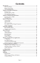
Contents Introduction ............................................................................................................. 4 Before You Begin ............................................................................................... 4 Manual Conventions ........................................................................................... 5 Warranty Registration ......................................................................................... 5 Windows 95/98/ME® Installation .....
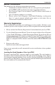
Introduction Introduction Thank you for purchasing the LynxTWO™! We are proud to provide you with a reliable, professional quality product for your digital audio requirements. This Installation and Users Guide provides basic information to help you get started. Before You Begin Before you begin the installation of your LynxTWO card, we recommend that you read through the Installation and Users Guide to acquire an overview of the installation procedure and use of the LynxTWO.
Introduction Manual Conventions This manual uses the following typographic conventions: • Underlined text denotes characters that are to be typed using the keyboard. • ALL UPPER CASE text denotes the names of specific connectors. • First Character Upper Case text denotes LynxTWO Mixer control names or menu options. • Italic text denotes emphasis or a warning.
Installation Windows 95/98/ME® Installation The procedure for installing the LynxTWO in Windows 95/98/ME requires that the LynxTWO Setup Program be run before you install your LynxTWO inside your computer. This program will install the required driver files needed for the Windows Plug-and-Play configuration manager to recognize the LynxTWO as a new device and will install the LynxTWO Mixer application. Running Setup 1. 2. 3. 4. 5. 6. 7.
Installation Windows NT/2000/XP® Installation The procedure for installing the LynxTWO in Windows NT/2000/XP requires that you install your LynxTWO inside your computer before the LynxTWO Setup Program is run. This program will install all the required driver files and the LynxTWO Mixer application as well as configure your system to recognize the LynxTWO. Installing the LynxTWO 1. 2. 3. 4. 5. 6. 7. 8. 9. Turn OFF the power to your computer system and disconnect the power cords.
External Connections External Connections The LynxTWO includes two break-out cables that provide connections for external equipment. The L2Audio cable provides XLR connectors for analog audio signals. The L2Sync cable provides XLR connectors for digital audio signals and female BNC connectors for clock input and output.
External Connections The nominal analog signal levels are compatible with either professional or consumer equipment. Use the Trim controls on the LynxTWO Mixer application to select +4dBu for balanced professional devices or –10dBV for balanced or unbalanced consumer devices. Please note that with 16 dB of headroom, the LynxTWO’s analog outputs are capable of delivering +20 dBu signal levels.
Using Your LynxTWO Using Your LynxTWO With the LynxTWO and its drivers properly installed in your computer, you can begin to use its capabilities with any third party audio application running under Windows or ASIO compliant applications under Macintosh OS. In order for these applications to access the LynxTWO you must select one of the LynxTWO audio devices in an application’s configuration menu for audio or wave.
Using Your LynxTWO Mixer Configuration Recall The state of the Mixer settings are saved each time Windows is shut down. The stored settings are automatically recalled the next time Windows is restarted. Clock Source Requirements A valid clock source signal must be connected to the appropriate LynxTWO clock connector when the Sample Clock Source is set to either Digital, External, or Header. If a signal is not present, the sample clock generator will run very slowly or erratically.
Using Your LynxTWO Windows Quick Audio Test The installation of your LynxTWO can be tested using the LynxTWO Mixer and the Sound Recorder application that ships with Windows 95/98/ME and Windows NT/ 2000. Any other audio application capable of audio recording and playback can be used in a similar manner. 1. Connect a stereo analog signal source to the IN 1 and IN 2 connectors on the Audio cable. 2.
Mixer Reference Mixer Reference The LynxTWO Mixer provides complete software control of the audio features of the LynxTWO and an indication of signal level during recording and playback. This section describes the function of each menu and control of the mixer. Mixer Menu With one LynxTWO installed in your computer the first selection in the Mixer Menu will be “LynxTWO Mixer” proceeded by a check mark.
Mixer Reference Rate – Displays the current sample clock rate of the LynxTWO. When the Sample Clock Source/Reference are set to Digital/Auto, External/Word, External/ Word256, Header/Word, or Header/Word256 the displayed sample rate must match the rate of the incoming clock being used for synchronization. This will ensure the correct sample rate is stored in the file’s WAV header, and that audio will playback at the correct sample rate.
Mixer Reference PCI Bus – The speed of the PCI Bus of the host computer. LTC Input – This section of the LynxTWO Mixer provides control of the Longitudinal Timecode Receiver. Lock – When lit, indicates the LTC Receiver is locked to an incoming signal. Direction – Indicates the direction of the timecode from the LTC Receiver. Drop Frame – Indicates if drop frame is specified for the incoming signal. Frame Rate – Indicates the actual frame rate of the LTC Receiver.
Mixer Reference Record Window Record Source Selection – Provides selection for the source of each associated record channel. Each channel may take its source from any one of the 24 available inputs. Peak Meters – Displays the instantaneous level of the audio being sent to the LynxTWO. Mute – Provides a mute function for each associated input. Dither – Enables / Disables dither for each associated input. The Dither type is specified in the Adapter window.
Mixer Reference Outputs Window Overload Indicator – Provides instantaneous overload indication of the audio being played or monitored. Once an overload condition has occurred the overload indicator remains until reset manually by the user by clicking on the control. Peak Meters – Displays the instantaneous level of the audio being played or monitored. Volume Faders – Controls digital attenuation of the audio being played or monitored. This control acts on the digital signals before D/A conversion.
Working with Third Party Applications Working with Third Party Applications Compatibility The drivers included with your LynxTWO provide compatibility with all standard third party audio editing applications that communicate with Windows Wave audio, DirectSound and ASIO devices. A list of applications that have been tested for compatibility is provided on the Lynx web site at http://www.lynxstudio.com/swlist.html.
Working with Third Party Applications The LynxTWO supports file types with 8, 16, 24, or 32 bit word widths. Note that 32bit files contain 24-bit data with zero data in the least significant bit positions. The LynxTWO Mixer application displays the currently selected bit depth for each device just above the device name in the Record window and the Play window.
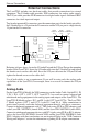
Configuring Multiple LynxTWO’s Configuring Multiple LynxTWO’s More than one LynxTWO card can be installed in a computer for additional audio channels. If required, all LynxTWO’s in a computer can be configured to maintain sample accurate synchronization during digital audio recording and playback. Cards are synchronized in a master-slave arrangement. One card is selected as the master which provides the word clock source for the other slave cards in the system.
Configuring Multiple LynxTWO’s 4. 5. Listen to the playback of any wave file and note which LynxTWO card is generating the audio signal. In this case, the card generating audio is adapter 1. Repeat steps 3 and 4, for “LynxTWO 2 Play 1”, “LynxTWO 3 Play 1”, and so on until all LynxTWO’s in your system have been identified. The next step is to choose which LynxTWO will act as a master.
Troubleshooting Troubleshooting When Windows starts I see a LynxTWO Mixer error - “No mixer device drivers are available”. This error will appear when the LynxTWO Mixer is loading during Windows startup and the LynxTWO is not installed correctly. You should check the following items: 1. With the computer power off, verify that the card is properly seated in the PCI slot. 2. Verify the LynxTWO’s resources are not conflicting with some other device in your system.
Troubleshooting Audio playback sounds fast or slow when I am using the digital input as the clock source. When the digital input is selected as the clock source, the LynxTWO’s sample clock will run at the sample rate of the incoming digital input signal. In the case when the sample rate of this signal is 48 kHz and a file being played was actually recorded at 44.1 kHz, the audio will playback fast.
Troubleshooting Can the LynxTWO share interrupts with other devices? The LynxTWO is able to share interrupts with other PCI devices, as long as the other PCI device’s driver is written correctly to share interrupts. The LynxTWO is not able to share interrupts with ISA devices (such as a modem, serial port, printer port, keyboard or mouse). The BIOS on many motherboards require the user to manually reserve an interrupt (IRQ) for an ISA device.
Support Support We are devoted to making your experience with LynxTWO trouble-free and productive. If you have questions or comments regarding the operation of your LynxTWO please check the “Troubleshooting” section of this manual and the FAQ and Troubleshooting topics on the Support section of the Lynx web site at: http://www.lynxstudio.com/support.html If you are unable to find information about your problem please email us at: support@lynxstudio.
Appendix Appendix Specifications Analog I/O A Model B Model C Model Type Level Input Impedance Output Impedance Output Drive Capability A/D and D/A Type Sample Rates Bit Depth On-board Buffer Size Analog In Performance Frequency Response Dynamic Range Signal-to-Noise Channel Crosstalk THD+N Analog Out Performance Frequency Response Dynamic Range Signal-to-Noise Channel Crosstalk THD+N Four inputs / four outputs Two inputs / six outputs Six inputs / two outputs Electronically balanced or unbalanced, XLR
Appendix SMPTE Time Code I/O Type Frame Rates Input Sync Rate Input Levels Output Level LTC receiver (in) and generator (out) , BNC connectors on L2Sync Cable 24, 25, 29.97, 30 Hz - drop and non-drop 1/30 to 80 times nominal frame rate 200 mV to 10V / 10KΩ 1V / 75Ω Clock I/O Number Level / Impedance Type External: one input and output, BNC connectors on L2Sync Cable Internal: one input and output on board-mounted headers TTL (clock signals) / 1Vpp (video) 75Ω Input: word clock, 256X word clock, 13.
Appendix XLR Connector Wiring and Adapters This section describes the proper wiring of cables that can be used to adapt both the analog and digital audio XLR connectors on the LynxTWO Audio Cable.
Appendix The wiring method for unbalanced connections with XLR connectors to RCA/Phono phone connectors using shielded twisted pair cable (2 wire + shield) is as follows: XLR Pin 1 (GND) to cable shield with no connection on the other end XLR Pin 2 (+) to signal wire and to the Phono center pin XLR Pin 3 (-) to the other signal wire and to the Phono sleeve XLR Male or Female 2 Conductor shielded cable RCA/Phono Plug (Unbalanced) 1 2 3 Unbalanced Connections with Single Conductor Cable In some cases it
Appendix The wiring method for unbalanced connections with XLR connectors to unbalanced RCA/Phono phone connectors using coaxial cable (1 wire + shield) is as follows: XLR Pin 1 (GND) no connection XLR Pin 2 (+) to signal wire and to the Phono center pin XLR Pin 3 (-) to the cable shield and to the Phono sleeve XLR Male or Female Single conductor shielded cable 1 2 3 Page 30 RCA/Phono Plug (Unbalanced)
Appendix Connector Pinouts L2Audio Port The L2Audio Port is a female 25-pin D-connector with the following connections: Pin 1 2 3 4 5 6 7 8 9 10 11 12 13 Signal O UT 4 Hot O UT 4 Gnd IN 4 Cold O UT 3 Hot O UT 3 Gnd IN 3 Cold O UT 2 Hot O UT 2 Gnd IN 2 Cold O UT 1 Hot O UT 1 Gnd IN 1 Cold none Pin 14 15 16 17 18 19 20 21 22 23 24 25 Signal O UT 4 Cold IN 4 Hot IN 4 Gnd O UT 3 Cold IN 3 Hot IN 3 Gnd O UT 2 Cold IN 2 Hot IN 2 Gnd O UT 1 Cold IN 1 Hot IN 1 Gnd The LynxTWO B Model replaces IN 3 and IN 4 wit
Appendix Instructions to the User This equipment has been tested and found to comply with the limits for a class B digital device, pursuant to part 15 of the FCC Rules. These limits are designed to provide reasonable protection against harmful interference in a residential installation. This equipment generates, uses and can radiate radio frequency energy and if not installed and used in accordance with the instructions, may cause harmful interference to radio communications.
Appendix EMC Certifications FCC DECLARATION OF CONFORMITY TRADE NAME: MODEL NUMBER: COMPLIANCE TEST REPORT NUMBER: COMPLIANCE TEST REPORT DATE: RESPONSIBLE PARTY (IN USA): ADDRESS: TELEPHONE: Computer Audio Card LynxTWO B10305A1 March 23, 2001 Lynx Studio Technology, Inc. 1048 Irvine Ave # 468, Newport Beach, CA 92660 (949) 515-8265 This equipment has been tested and found to comply with the limits for a Class B digital device, pursuant to Part 15 of the FCC rules.
License Agreement This legal document is an agreement between you and Lynx Studio Technology, Inc. By opening the sealed board package, or written materials, you are agreeing to become bound by the terms of the agreement, which includes this License and Limited Warranty (collectively the “Agreement”). This Agreement constitutes the complete agreement between you and Lynx Studio Technology, Inc. If you do no agree to the terms of the Agreement, DO NOT OPEN the anti-static bag containing the LynxTWO board.
Page 35