
Operation Manual

Operational Overview
AES16e User Manual
Page 33
5 Operational Overview
5.1 Signal Flow
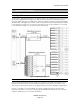
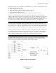
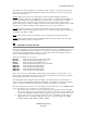
As shown in the signal flow diagram below, the AES16e with its on-board digital mixer provides extensive
signal routing capabilities that can adapt to any studio requirement. The mixer is implemented using a
proprietary digital signal processor (DSP) that is optimized to maintain low latency and high signal quality.
The architecture of the digital mixer consists of 16 record channels and 16 play channels that are accessible
to host applications as eight stereo record devices and eight stereo play devices. Submixers on each output
provide low-latency mixing for record monitoring and output mixing.
Figure 6: Signal Flow Diagram
5.1.1 Physical Inputs
Starting from the digital inputs in the upper right portion of Figure 6, each AES-3 input signal is routed
through a transformer for isolation before arriving at an AES-3 receiver. The receiver extracts a word-
clock, using a low jitter phase-locked loop, and signal data that is passed to the Input Bus of digital mixer.
In the case of the SRC version of the AES16e, the signals on digital inputs then pass through a high-
performance sample rate converter before merging with the Input Bus. This sample rate converter can be
enabled or disabled under user control in the Lynx Mixer.