Reference Manual DOC. REV. 3/16/2009 EPM-4 (Lynx) AMD ÉlanSC520 processor module with 10/100 Ethernet, and PC/104-Plus interface.
EPM-4 AMD ÉlanSC520 processor module with 10/100 Ethernet, and PC/104-Plus interface MEPM4
Product Release Notes This page includes recent changes or improvements that have been made to this product. These changes may affect its operation or physical installation in your application. Please read the following information. Rev 5 Release • EPM-4h model release – RoHS extended temperature version. Rev 4 Release • PC/104 (ISA) connector keyed to better comply with standard. PC/104 connector soldered instead of press-fit. • Physically smaller fuse at F1 with same protection value. • 3.
Model EPM-4 AMD Élan processor module with 10/100 Ethernet, and PC/104-Plus interface REFERENCE MANUAL VERSALOGIC CORPORATION WWW.VERSALOGIC.
Table of Contents Introduction ..................................................................................................................... 1 Description.......................................................................................................................... 1 Technical Specifications ..................................................................................................... 2 EPM-4 Block Diagram ............................................................................
Table of Contents Connector Location Diagram............................................................................... 20 Connector Functions and Interface Cables .......................................................... 21 Jumper Block Locations ................................................................................................... 22 Jumper Summary ................................................................................................. 23 Power Supply...........................
Table of Contents Appendix B — References ...........................................................................................
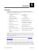
1 Introduction Description The EPM-4 (Lynx) is a 486-based processor board in a compact PC/104-Plus format. It is specifically designed for OEM control projects requiring compact size, high reliability, and long product lifespan / availability.
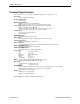
Technical Specifications Technical Specifications Specifications are typical at 25°C with 5.0V supply unless otherwise noted. Board Size: 3.55" x 3.775" (PC/104 standard). Storage Temperature: –40° C to 85° C Operating Temperature: EPM-4c, g 0° C to +60° C (100 FPM airflow) EPM-4e, h -40° C to +85° C (free air, extended temperature versions) Power Requirements: (with keyboard, mouse, and hard drive running DOS) EPM-4c, g 133 MHz +5V ±5% @ 0.94A EPM-4e, h 100 MHz +5V ±5% @ 0.
EPM-4 Block Diagram EPM-4 Block Diagram EPM-4 Reference Manual Introduction – 3
RoHS-Compliant Version RoHS-Compliant Version The EPM-4g and EPM-4h are RoHS-compliant. These models are functionally identical to the non-RoHS version of the boards. ABOUT ROHS In 2003, the European Union issued Directive 2002/95/EC regarding the Restriction of the use of certain Hazardous Substances (RoHS) in electrical and electronic equipment.
Technical Support Technical Support If you have problems that this manual can’t help you solve, first visit the EPM-4 Product Support web page below. If you have further questions, contact VersaLogic for technical support at (541) 485-8575. You can also reach our technical support engineers via e-mail at Support@VersaLogic.com. EPM-4 Support Website http://www.VersaLogic.com/private/lynxsupport.
Configuration / Operation 2 Overview ELECTROSTATIC DISCHARGE Warning! Electrostatic discharge (ESD) can damage boards, disk drives, and other components. The circuit board must only be handled at an ESD workstation. If an approved station is not available, some measure of protection can be provided by wearing a grounded anti-static wrist strap. Keep all plastic away from the board, and do not slide the board over any surface.
Initial Configuration and Setup Initial Configuration and Setup The following list describes the components recommended for setting up a typical development system.
CMOS Setup / Boot Procedure CMOS Setup / Boot Procedure • • • • • • Turn power on. Press the DEL key the instant that video is displayed (during the memory test). Verify default CMOS Setup information as shown below. Insert bootable floppy disk into floppy drive. Reset computer using push button reset. See VersaLogic KnowledgeBase article VT1476 – EPM-4 CMOS Setup Reference for more information about these parameters.
Console Redirection Console Redirection If there is no video device detected during boot up, BIOS keyboard and screen I/O can be redirected to the COM2 RS-232 serial port. CMOS configuration can be modified over this redirected console. ANSI or VT102 terminal emulation is recommended. When console redirection is enabled, press CTRL-C on the terminal emulator to enter CMOS Setup; the BIOS ignores DEL from a PS/2 keyboard. This is normal operation of the Lynx.
CMOS Setup / IDE Configuration CMOS Setup / IDE Configuration IDE The Lynx has a single IDE channel to connect up to two hard disks, CompactFlash modules or CD-ROM drives. This basic IDE interface operates using PIO mode 0, resides on the ISA bus, and does not support the drive address register at I/O address 3F7h. It has been tested successfully on a wide variety of operating systems. IDE SETUP IDE devices include hard disk drives, CD-ROM drives, and some CompactFlash modules.
CMOS Setup / Advanced Configuration Usually, the drive you specify here corresponds to the declaration in the Drive Assignment Order field. A CD-ROM drive can be inserted into the boot order by selecting “CDROM” at the desired boot order position. CMOS Setup / Advanced Configuration D0000H 64K PAGE FUNCTION Default: ISA bus ISA bus Memory accesses to the D0000h page will be sent to the ISA bus for use by PC/104 expansion modules. This setting is required when flashing the BIOS with the FBU utility.
CMOS Setup / Advanced Configuration PS/2 MOUSE (IRQ12) Default: Enabled When disabled, IRQ12 is freed for other devices. LPT1 (0378H) Default: IRQ7 Allows you to disable or specify the IRQ used by LPT1 on the SMSC FDC37B727 Super I/O. When disabled, the IRQ and I/O space are freed. PARALLEL PORT MODE Default: SPP This option allows the user to change the communication mode of the parallel port. The options are: SPP, SPP/EPP1.9, ECP, ECP/EPP1.9, Printer, SPP/EPP1.7, ECP/EPP1.7, and FDD.
CMOS Setup / Advanced Configuration COM1 (03F8H) RS-232 Default: IRQ4 Allows you to disable or specify the IRQ used by internal UART1 on the ÉlanSC520 Microcontroller. When disabled, the IRQ and I/O space are freed. COM2 (02F8H) RS-232 Default: IRQ3 Allows you to disable or specify the IRQ used by internal UART2 on the ÉlanSC520 Microcontroller. When disabled, the IRQ and I/O space are freed.
Using Custom CMOS Defaults Using Custom CMOS Defaults The Lynx BIOS has the capability to store CMOS defaults in the on-board flash chip. This storage area is non-volatile, enabling the Lynx to run with user-specified CMOS defaults without a battery installed. If custom defaults are specified, they will be used instead of the factory defaults any time CMOS memory needs to be reset.
Reference 3 Physical Dimensions 3.470 3.050 0.150 The EPM-4 complies with all PC/104-Plus standards. Dimensions are given below to help with pre-production planning and layout. 3.575 3.370 3.070 2.330 0.400 3.300 0.000 -0.200 3.570 3.350 3.150 0.000 0.200 -0.250 Figure 1. Dimensions (Not to scale. All dimensions in inches.
Physical Dimensions HEIGHT DIMENSIONS 0.44 0.51 0.42 0.44 0.06 Figure 2. Height Dimensions (Not to scale. All dimensions in inches.
Physical Dimensions HARDWARE ASSEMBLY The EPM-4 uses pass-through PC/104 and PC/104-Plus connectors so that expansion modules can be added to the top or bottom of the stack. PC/104 (ISA) modules must NOT be positioned between the Lynx and any PC/104-Plus (PCI) modules on the stack. The PC/104 pass-through connector on the EPM-4 Rev 4 is keyed (pins B10 and C19 missing) to provide greater compatibility with other PC/104 compliant devices.
External Connectors External Connectors CONNECTOR LOCATION DIAGRAM Figure 4. Connector Locations On the EPM-4 Rev 4 and above, the pass-through PC/104 (ISA) connector is keyed (pins B10 and C19 missing) for greater compatibility with PC/104 devices, as shown in the figure below. Pin Side of ISA Connector C19 B10 B32 A32 B1 A1 C19 D19 C0 D0 Pin numbering begins on the side with a larger row offset Note: For rows A and B, pin numbers begin at 1. For rows C and D, pin numbers begin at 0. Figure 5.
External Connectors CONNECTOR FUNCTIONS AND INTERFACE CABLES The table below notes the function of each connector, as well as mating connectors and cables, and the page where a detailed pinout or further information is available. Note: VersaLogic adapter cables for the EPM-4 are available in RoHS compliant and RoHS noncompliant versions. Compliance or noncompliance is indicated by the part number prefix. “CBR” indicates RoHS compliance. “CBL” indicates RoHS noncompliance.
Jumper Block Locations Jumper Block Locations Note: The diagram below shows the as-shipped configuration for jumpers on Rev. 4.xx and earlier boards. On Rev. 5.xx and later boards, no jumper is installed on V3. Figure 6.
Jumper Block Locations JUMPER SUMMARY Table 2: Jumper Summary Jumper Block Description As Shipped Page V1 Battery Power Jumper [1-2] In – Discharge CMOS Memory [2-3] In – Standard Operation [2-3] In 26 V2 COM3 configuration [1-2] In [3-4] In 27 [5-6] In [7-8] In 27 [1-2] In and [3-4] In – RS-485 Endpoint [1-2] In and [3-4] Out – RS-485 Intermediate [1-2] Out and [3-4] In – RS-422 V2 COM4 configuration [5-6] In and [7-8] In – RS-485 Endpoint [5-6] In and [7-8] Out – RS-485 Intermediate [5-6]
Power Supply Power Supply POWER CONNECTORS Main power is applied to the EPM-4 through a 10-pin polarized connector. Mating connector Berg 69176-010 (Housing) + Berg 47715-000 (Pins). See the table below for connector pinout and page 20 location information. Warning! To prevent severe and possibly irreparable damage to the system, it is critical that the power connectors be wired correctly. Make sure to use all three +5VDC pins and all four ground pins to prevent excess voltage drop.
Power Supply POWER REQUIREMENTS The EPM-4 only requires +5 volts (±5%) for proper operation. The voltage required for the RS232 ports is generated with an on-board DC/DC converter. A variable low-voltage supply circuit provides power to the CPU and other on-board devices. The exact power requirement of the EPM-4 depends on several factors peripheral connections, type and number of expansion modules, and attached devices.
CPU CPU The ÉlanSC520 Microcontroller has a 32-bit, low-voltage AMD Am5x86 microprocessor at its core. The maximum clock rate is 133 MHz. The Am5x86 has 16 kb of unified cache that supports write-back and write-through policies. It is a high-performance 486 CPU achieving performance results equal to a Pentium 75. System RAM MEMORY The EPM-4 has 64MB of SDRAM soldered on board. • • • • • Storage Capacity Voltage Error Detection Code Error Correction Speed 64 MB 3.
Battery Backed Static RAM Battery Backed Static RAM The EPM-4 can be ordered with an optional 2 MB of Battery Backed Static RAM (BBSRAM). This BBSRAM is powered by the boards RTC battery when main power is turned off. Jumper V1, which is used to clear CMOS RAM, does not affect the BBSRAM. The BBSRAM is located at the absolute address of (0x08000000) in one continuous 2 MB block. Serial Ports The EPM-4 features two on-board 16550 based serial channels located at standard PC I/O addresses.
IDE Hard Drive / CompactFlash / CD-ROM Interface IDE Hard Drive / CompactFlash / CD-ROM Interface One IDE interface is available to connect up to two IDE devices, such as hard disks, CD-ROM drives or CompactFlash (CF) media. Use CMOS Setup to specify the drive parameters of the attached drives. An activity indication LED is provided on the EPM-4. The yellow LED of D5 (See page 22) will show that activity is detected on the IDE interface.
Utility Connector (J7) Utility Connector (J7) The 50-pin utility connector (J7) incorporates the COM ports, keyboard and mouse, generalpurpose inputs, and the reset button and speaker. Table 5 shows the function of each pin and the pinout to the connectors of the CBL/CBR-5009 I/O board.
Utility Connector (J7) KEYBOARD/MOUSE INTERFACE A standard PS/2 keyboard and mouse interface is accessible through connector J7. This device is protected against ESD damage by IC 61000-402 rated transient voltage suppressor components. PROGRAMMABLE LED The high-density I/O connector J7 includes an output signal for attaching a software controlled LED. Connect the cathode of the LED to J7[48]; anode to J7[47]. An on-board resistor limits the current to 15 mA when the circuit is turned on.
Parallel / Floppy Port Parallel / Floppy Port PARALLEL PORT OPERATION The EPM-4 includes a standard bi-directional/EPP/ECP compatible LPT port which resides at the PC standard address of 378h. The port can be enabled or disabled and interrupt assignments can be made via the CMOS setup screen. The LPT mode is also set via the CMOS setup screen. This connector uses IEC 61000-4-2-rated TVS components to help protect against ESD damage.
Ethernet Interface Ethernet Interface The EPM-4 features an industry-standard 10baseT / 100baseTX Ethernet interface based on the Intel 82551ER Ethernet controller. This PCI based interface chip is widely supported. Drivers are readily available to support a variety of operating systems such as QNX, VxWorks and other RTOS vendors. BIOS CONFIGURATION The Ethernet interface shares PC/104-Plus interrupt “INTC”. The CMOS Setup screen is used to select the IRQ line routed to INTC*.
Watchdog Timer Watchdog Timer There is a flexible watchdog timer integrated into the ÉlanSC520 Microcontroller. It supports a time-out period up to 30 seconds, and can generate an interrupt, NMI, or system reset when timeout occurs. The watchdog registers are protected by write key sequences. See the following pseudo code as a simple example of watchdog operation.
Expansion Bus Expansion Bus The EPM-4 will accept up to eight expansion modules, up to four of which can be PC/104-Plus (PCI) expansion modules. The EPM-4 uses 3.3V PCI signaling but is 5V tolerant. PC/104-PLUS (PCI BUS) PC/104-Plus modules can be secured directly to the top or bottom of the EPM-4. Make sure to correctly configure the "slot position" jumpers on each PC/104-Plus module appropriately. PC/104 modules must not be positioned between the EPM-4 and any PC/104-Plus modules on the stack.
Expansion Bus PC/104 Modules PC/104 I/O modules should be addressed in the 104h – 3FFh address range. Care must be taken to avoid the I/O addresses shown in the On-Board I/O Devices table on page 37. These ports are used by on-board peripherals and video devices.
Memory and I/O Map Memory and I/O Map ÉLANSC520 MEMORY MAPPED CONFIGURATION REGION (MMCR) REGISTERS Much of the functionality incorporated into the ÉlanSC520 Microcontroller, such as the watchdog timer, CPU speed control, and general-purpose timer, can be controlled and monitored through the Memory Mapped Configuration Region (MMCR) registers. The MMCR registers occupy 4KB of memory space. For convenience, these registers are made available at boot time in the first megabyte of system RAM, at DF000h.
Memory and I/O Map I/O MAP The following table lists the common I/O devices in the EPM-4 I/O map. User I/O devices should be added in the 104h – 3FFh range, using care to avoid the devices already in the map as shown below.
Interrupt Configuration Interrupt Configuration Default interrupt settings on the Lynx have been selected to maintain PC/AT compatibility. They can be re-routed to satisfy customer constraints. Use the custom configuration screen in BIOS setup to configure IRQ’s on the Lynx Not all devices can use all IRQ’s. Refer to Figure 8 for a description of allowable IRQ assignments for each device. Figure 8. Interrupt Circuit Diagram Components Group: COM1, COM2, GP Timers, Watchdog, PCI Interrupts.
Special Control Register Special Control Register SCR (READ/WRITE) 00E0h D7 D6 D5 D4 D3 D2 D1 D0 Reserved Reserved SB-SEL Reserved Reserved Reserved Reserved GPI Table 10: Special Control Register Bit Assignments Bit Mnemonic D7-D6 — D5 SB-SEL D4-D1 — D0 GPI Description Reserved — These bits have no function.
Revision Indicator Register Revision Indicator Register REVIND (READ ONLY) 00E1h D7 D6 D5 D4 D3 D2 D1 D0 PC4 PC3 PC2 PC1 PC0 REV1 REV0 ET This register is used to indicate the revision level of the EPM-4 product. Bit Mnemonic D7-D3 PC4-PC0 D2-D1 REV1-REV0 D0 ET Description Product Code — These bits are hard coded to represent the product type. The EPM-4 will always read as 11011. Other codes are reserved for future products.
Map and Paging Control Register Map and Paging Control Register MPCR (READ/WRITE) 00E3H D7 D6 D5 D4 D3 D2 D1 D0 FPGEN Reserved Reserved Reserved Reserved PG2 PG1 PG0 Table 11: Map and Paging Control Register Bit Assignments Bit Mnemonic D7 FPGEN Description FLASH Paging Enable — Enables a 64KB page frame from E0000h to EFFFFh. Used to gain access to the on-board FLASH memory. FPGEN = 0 FLASH page frame disabled. FPGEN = 1 FLASH page frame enabled.
Appendix A — CBL/CBR-5009 A CBL/CBR-5009 Connectors Figure 9. CBL/CBR-5009 Connector and Component Locations Table 12: Connector/Component Functions, and Interface Cables Connector / Component Function Part Number Description LEDx2 T1 3/4 PC Mount Red/Red D1 Power and Programmable LEDs Dialight 552-0211 J1 High Density Connector FCI 98414-F06-50U 2mm, 50 pins, keyed, latching header J2 Timer and Reset input Conta-Clip 10250.
Map and Paging Control Register CBL/CBR-5009 Dimensions and Mounting Figure 10.
Appendix B — References B Integrated 32-bit CPU ÉlanSC520 Advanced Micro Devices, (www.amd.com/epd) Ethernet Controller 82551ER Intel Corporation, (www.intel.com/design) PC/104 Specification PC/104 Resource Guide PC/104 Consortium, (www.pc104.org) PC/104-Plus Specification PC/104 Resource Guide PC/104 Consortium, (www.pc104.org) General PC Documentation The Programmer’s PC Sourcebook Microsoft Press (www.microsoft.