Copyright © 2014 Lynx Studio Technology Inc.
User Manual Table of Contents 1 Introduction ............................................................................................................... 1 1.1 1.2 1.3 1.4 1.5 1.6 Overview ........................................................................................................................ 1 Features .......................................................................................................................... 1 In the Box ..................................................
4.4.2 4.4.3 4.4.4 4.4.5 4.4.6 4.4.7 4.4.8 4.5 Tools Page.................................................................................................................... 40 4.5.1 4.5.2 4.5.3 4.5.4 4.5.5 4.5.6 4.5.7 4.6 4.8 Meter Button ................................................................................................................ 50 Lynx Website Support Resources ................................................................................ 51 Telephone Support ...................
1 Introduction Thank you for choosing Lynx Hilo for your audio needs. The device you have received has been precision engineered to provide the very best audio quality possible, coupled with an innovative, intuitive user interface, and a unique and powerful feature set. Hilo is one of the first pro audio devices on the market that utilizes a full-color LCD touchscreen for control, metering and configuration.
1.4 Power and Safety Information To prevent fire or shock hazard, do not expose this equipment to rain or moisture. Do not block any of the ventilation openings. Do not defeat the safety purpose of the grounding-type plug. A grounding type plug has two blades and a third grounding prong. The third prong is provided for your safety. If the provided plug does not fit into your outlet, consult an electrician for replacement of the obsolete outlet.
1.6.2 Computer requirements Hilo is configured to operate with Mac or PC computer systems via a Thunderbolt connection. If one wishes to use this connection, check the system requirements below to insure compatibility. There are three essential elements that must be met for compatibility with the Hilo with Thunderbolt: 1. The host computer must have one or more compatible and functional Thunderbolt ports. 2.
1.6.3 Compatible Firmware If the LT-TB is being installed into the Hilo, it is critical that the Hilo have firmware revision 6 or higher. Before installing the card, we recommend verifying the firmware version, and updating it through the USB connection to the computer, before replacing the LT-USB card in the Hilo with the LT-TB. To verify the firmware revision, on the Hilo front panel navigate to the Information Screen, then tap “About Hilo”.
2 Getting Started Hilo was designed to be a product that is so easy to use that this section of the manual would scarcely be necessary. However, it is quicker to learn how the device works in one go, then to spend precious minutes figuring things out by randomly pressing buttons. We recommend reading this section thoroughly, before putting Hilo to serious use. 2.1 Unpacking Before setting up Hilo for use, remove it from the box and verify that the box contents described in section 1.3 are all present.
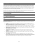
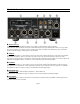
2.3 Cable Connections Hilo features a treasury of I/O types, suitable to accommodate whatever audio devices you wish to integrate. q Thunderbolt port Use a copper or optical Thunderbolt cable to connect Hilo to a Thunderbolt equipped computer. Cable Concerns: The LT-TB has been tested with standard optical and copper Thunderbolt cables. For Copper cable, one can use lengths up to 3 meters (9.8 feet).
y S/PDIF/ ADAT Optical Use standard Toslink optical cables, of lengths up to 9 meters (30 feet). u SPDIF Coaxial In Out Use 75 Ω S/PDIF cable with RCA connections. Recommended maximum length is 6 meters (20 feet) i Wordclock In/Out Use standard 75 Ω wordclock cable with BNC connectors. Recommended maximum length is 9 meters (30 feet). o Battery In DC 4-pin XLR battery pack connector. Supports 9-18 volts DC. See Appendix 5.1 for more information.
Thunderbolt cables are somewhat unique in that they contain signal transmission electronics. For this reason it is important to practice good cable management, avoid crimping or allowing cables to be compressed. If such practices are adhered to, these cables should provide many years of faithful service. Connect a cable from the Thunderbolt port on your computer to either of the ports on the back of the Hilo/TB. Then turn the unit ON. 2.5.
5. Accept the License Agreement by clicking “Accept” 6. The installer will extract the necessary files to the C:\Lynx directory. Click “Extract” from this window 7. If you are prompted to let the program make changes to the computer, select “Yes” 8. You will next see the driver Install dialog. Click “Install” 9. You may get a Windows Security Dialog Bog. If so, select “Install” 10.
11. Finally you will receive a confirmation that the install completed successfully 12. The Hilo is ready to use, no reboot necessary. 2.5.2.2 OS X 1. Locate the LT-TB driver from your downloaded files. The file name will be Lynx_OSX_xxxx.zip. Doubleclick to expand the installer package. 2. Double-click “Lynx OSX.pkg” that was expanded from the step above. This will start the driver installation. 3. Click “Continue” at the “Install Lynx CoreAudio Driver Installer” dialog box. 4.
5. Click “Agree” from the next Window 6. Click “Install” in the Standard Install Window 7. Type in Password and click “Install Software” 8. Click “Continue Installation” for prompt about restarting computer after the installation 9.
10. When complete, you will be prompted to restart the computer After restart the driver will be installed and ready for use. 2.6 Using Multiple Hilos and/or Auroras Up to six Lynx Aurora/TB and/or Hilo/TB interfaces can be daisy chained to a single Thunderbolt port. Each unit will be addressable independently, and the combined I/O can be used by a DAW application. Connecting multiple units requires consideration of the following: 2.6.
2.6.3 Set the Sync Source Whenever multiple Hilos and Auroras are used in a Thunderbolt daisy-chain, it is critical that clock synchronicity is achieved. In the vast majority of cases we would recommend one of the following clock schemes: - Use a master clock with multiple clock outputs, ideally as many outputs as there are Hilos in the chain, and connect each Hilo to a unique word clock connection. In this case, ALL of the Hilos should be set to “EXT” as the SYNC SOURCE.
Also make sure that the checkboxes for “Built-In” audio are un-checked. Now, your multi interface LT-TB Aggregate Device is ready to use from within your favorite Audio application. 2.7 Using LT-TB with other Thunderbolt Devices The Thunderbolt specification requires that certified units can allow for daisy chaining other Thunderbolt devices.
3 Using the Hilo/TB With the LT-TB correctly installed in your computer, you can begin to use the Hilo with most popular third-party audio applications. In this section we will explore setting up the Hilo/TB system for different contexts of use. 3.1 Hilo Driver Devices – Windows Operating Systems Hilo was designed to provide maximum compatibility with the most popular audio and multimedia applications that use the Windows MME, DirectSound, ASIO and OS X Core Audio driver standards.
3.1.2 ASIO Application When using an application that supports the ASIO driver standard, one must specify the Lynx ASIO driver as the active audio device from within the audio software. Once that is established, eight stereo input and output devices will be available for use within the application. When using an ASIO compatible program, the appropriate ASIO device must be selected from a settings or options menu in the application.
3.1.3 Controlling Latency by Changing the Buffer Size Latency in an audio interface can be defined as the time required to process a sample from an application to the interface’s audio output. A number of factors determine the achievable latency performance of a Hilo/ TB system: processor speed, operating system, sample rate, number of utilized record or play channels, system efficiency, etc. Latency can be manipulated by changing the size of the buffers used to transfer data to and from the LT-TB.
When the Lynx Hilo is selected as the output sound device, channels 1&2 are active by default. In this state, audio will be sent to ALL Hilo outputs simultaneously. If you wish to mute a stream to a particular output, you can do that from the Output Mix Routing Page, as describe in section 3.4.2 Output Mix Routing Page. 3.2.1.
on Windows and OSX can be downloaded from the Lynx Studio website. Here are the steps to insure that your Hilo is up to date and in top form: 1. 2. 3. 4. 5. 6. 7. 8. Make sure that your Hilo has a valid Thunderbolt connection to the computer. It is essential that current drivers are installed and operational. Visit www.lynxstudio.com and click Support > Downloads. Select your OPERATING SYSTEM from the list, “Hilo” as the PRODUCT, and “All Types” for FILE TYPE.
9. Launch the AES16e/LT-TB Update application. 10. Verify that the New Firmware Version is higher than the Current Firmware Version. If so, click “Update” 11. Follow the prompts. When the updater is complete, you will be prompted to turn the computer off (not a reboot). Click “POWER OFF” and the computer will be shut off automatically. Wait three seconds, then turn the computer back on. 12. The new LT-TB firmware will now be active.
4 Controlling Hilo Hilo’s Touch Screen gives it a key advantage over other converters. As all of the functions are controlled by the software that runs the touch screen, Hilo is not locked into just one way to work. We can add features. We can change the graphics. We can offer completely different user interfaces for different types of users. So the Hilo user interface in five years may be radically different than today’s Hilo. In short, it will evolve. You can help us with this.
Headphone and Monitor Out Volume Controls, or any three outputs selected in the “Knob Settings: menu. See section 3.7.6 4.
Touch on the type of meter you would like to see. The new meter will instantly appear. If no selection is made, clicking anywhere on the Touch Screen outside of the menu will cause the menu to close. 4.2.1 Choosing the Meter Source You can select any Input or Output Source to be shown on the Analog VU and Horizontal Meters. 4.2.1.1 For the Analog VU Meters: Touch the Monitor Source Selection button that is centered at the bottom of the screen.
4.3 Getting to the Menu Pages The in the lower right corner of any Meters page will send you initially to the Home page. Thereafter this will send you to the last Menu page that you accessed. The bottom of the menu pages has five round buttons which allow you to navigate between menu pages. The Meter button on the far left returns you to the active meter page. The four buttons on the right select menu pages, each with up to 8 functions.
4.4 Home Menu 4.4.1 Sample Rate Hilo will display the sample rate that it is currently operating at. If clocked externally, this may be the sample rate being generated by the clock source. If clocked Internally, the sample rate may reflect the rate of audio being played or the rate requested from an audio software application. If Hilo has the Sync Source set to Internal, then one can manually choose a sample rate by pressing the Sample Rate button and tapping on the desired rate.
4.4.2 Sync Source This button will show the currently selected Sync Source. When you push the Sync Source button, you may select any of six possible clock sync options. If a clock source is valid, a sample rate will appear next to that selection. For instance, if a clock source is connected to the Hilo word clock input, next to “Word Clock” there would appear the sample rate that the clock source is generating.
There are four possible states for the SynchroLock button. 4.4.4 Locked Either Hilo is operating off of its Internal clock, or SynchroLock has achieved full lock to the specified external clock source. In this state, playback and recording of audio is possible Working Hilo is operating off of its Analog Phase Lock Loop to lock to the incoming clock signal, while the SynchroLock circuitry is performing analysis on the incoming clock signal. This may continue for 1-2 minutes.
4.4.5 Line In Trim Line In Trim can be set to any of eight preset trim settings. The Line In Trim button shows the currently selected trim level, the same for the Left and Right inputs. There are four Pro Level settings: +18 dBu; +20 dBu; +22 dBu; and +24 dBu. There are four additional levels most often used on Consumer Audio products: +0 dBV; +2 dBV; +4 dBV and +6 dBV. When the button is pushed, a Selection Window pops up.
4.4.7 Digital In Source Hilo offers a choice of AES or S/PDIF as the digital input source. With S/PDIF you have the option of Coax or Optical Inputs. Before being pushed, this button shows the current selection. Upon pushing the button, you can select: AES; S/PDIF Coax; or S/PDIF Optical. If selecting SPDIF Optical, the Optical Out mode must be set to SPDIF. See section 3.4.4. Note: You do not need to make this choice for outputs, as all three digital outputs are independently available and assignable. 4.
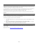
RED buttons mean that the associated signal source or output is OFF or MUTED GREEN buttons mean ON or UNMUTED A WHITE LINE around a button means this is the channel is in focus, and can be acted upon by the faders or ON/OFF switch below the fader. As you can see, the page is divided into input sources on the left and outputs on the right. What we are seeing here is which input sources are assigned to the displayed output.
4.4.8.1 Monitoring Modes The default state for each input source is stereo, with two channels of input, streaming through a two-channel output. There are 4 different options for routing an input signal to an output. These selections pertain to the operation of a specific input source routed to a specific output. The setting is not global, and must be set for each output that is being used. Select the Output channel that you wish to listen to, then press the desired input source (in this example, Line In).
4.4.8.2 Solo Button The Solo button allows any active input channel to be isolated. This allows very rapid comparison of sources, A/B switching, and a convenient way for troubleshooting audio anomalies. Simply press the Solo button and it will engage and turn green with the word “Solo” blinking. In this state, press any input source button and you will hear that audio exclusively. Pressing any other input source will instantly switch to the alternate source.
The Default TB play routings are: Line Out: Monitor Out: Phones: Digital Out XLR (AES): Digital Out Coax: Digital Out Optical: ADAT Out 1-8: 4.4.8.4 TBT 1+2 TBT 1+2 and 3+4 TBT 1+2 and 5+6 TBT 1+2 and 7+8 TBT 1+2 and 9+10 TBT 1+2 and 11+12 TBT 1+2 and 9-16 Outputs You may have noticed that, with the exception of the TBT play channels, all input sources are muted/off by default. The output sources are the opposite, all un-muted/on by default.
4.4.8.5 Analog and Digital Level Controls for Monitor and Headphones When the Monitor Out and Phones Outputs are selected in the Output Mix Routing Page, you will see an additional button. For these two outputs you can control both the Digital output level and the Analog output level. Analog Output Level – This is your primary monitoring level control. You can control this level / volume using the fader or the knob on the front panel.
There is an overload at indicator at the top of these meters. When potentially distortion-causing clipping occurs, this indicator turns red and the associated text reads “OVER”. For an input, the Over indicator will activate when there are three full-scale samples in a row, which indicates a high probability that clipping has occurred.
4.4.8.7 Selecting Monitor Sources Let’s look at the process of assigning input sources to Hilo’s Outputs Let’s say that we wanted to add Digital In as a source to route to the Line Out. We could simply enable the Digital In with either a single-tap or double-tap and the page would now look like this. In this state, audio streaming from TBT Play 1&2 will be merged with audio streaming from the Digital Input.
4.4.8.8 Adjusting levels of input sources and outputs The Output Mix Routing page has two faders, one on the input side and one on the output side. In both cases the single fader controls the level for two channels of audio. The fader on the input side adjusts the amount of signal from the input source that is in focus (with the white box around it) that is feeding the active output.
4.4.8.9 Routing tutorial These powerful routing features are probably best demonstrated with a real-world scenario. Let’s pretend that the Hilo is being used for a recording session, where a keyboard part is being overdubbed on an existing project. The prerecorded tracks are streaming through the TBT Play 1&2 channels in the computer. For cable connections, the keyboard signal is coming in LINE INPUTS 1&2. The recording engineer is listening to the MONITOR OUTPUTS feeding speakers in the control room.
Now let’s pull up the Phones Out to adjust the performer’s levels. Again, Play 1&2 is pre-assigned as a source. Now we’ll add Line In, so the performer can hear their input signal This performer likes the levels of the backing tracks louder, but the overall level down a bit, so we’ll nudge the Play source signal up by 6dB, and attenuate the Phones output by 10dB Now the performer and engineer each have their own monitor mix.
4.5 Tools Page 4.5.1 Restore Default Routing This button restores the factory default settings. It is quite useful as a troubleshooting tool. Generally, it is recommended to save a scene when a custom configuration has been established (described below), but restore defaults is a very speedy way to know if an errant setting is producing performance problems. 4.5.2 Save Scene Button Once you have created a specific routing/level set up that you may want to recall, here is where you would store it.
Scene 1 to 6 for storage. The QWERTY keyboard screen will come up and you can name the scene using up to 13 characters Input the Scene name using your fingers (or some pointed, non-abrasive pointer such as pencil eraser, pen end or even a chop stick). To clear the entire name, tap the Clear button. To backspace and clear one letter at a time, tap the Back button. Tapping the Cap button will capitalize the letters but keep the row of numbers.
4.5.4 Sample Rate Converter Hilo features a powerful Sample Rate Converter for the AES and SPDIF Inputs. When active, the onboard SRC processor supports for conversion ratios up to 16:1 with 144 dB dynamic range and -140dB THD+N. The SRC will convert signals on the active Digital Input up or down to the current Sample Rate.
audio in DoP V1.1 is automatically detected on either Hilo TBT input 1 & 2 or the selected Digital In Source. If DSD is detected on both of these sources, priority is given to TBT input 1 & 2. NOTE: When the DSD Mode is set to Off, incoming data will be processed as standard linear PCM data always. If DSD audio is received in this mode, low volume noise will be played.
4.5.7 Power Up State Hilo can be set to toggle between two power up states: Standby: In this mode, when AC power is applied and the back panel power switch is in the ON position (show graphic), Hilo will be in Standby mode until the front panel STANDBY switch is pressed. Then the Hilo will power up and be ready for use. On: In this mode, when AC power is applied and the back panel power switch is in the ON position, Hilo will power up and be ready for use.
4.6.1 Digital In Channel Status This section displays status information pertaining to the Hilo’s digital inputs. The data displayed indicates the quality of the AES/EBU connections as well as channels status data sent by a transmitting device. The information displayed in this section is very useful for troubleshooting digital input connection issues.
For each of the three possible Digital Outputs (AES, SPDIF Coax, SPDIF Opt you can select one or more: • Validity This checkbox controls the state of the Valid bit. When checked, the Valid bit is turned on to indicate to the receiving device that the audio data being transmitted is valid. This is the default state. • Non-PCM This checkbox controls the state of the Non-PCM channel status bit.
4.7 Display Controls These controls allow you to customize how you want the LCD screen to work and what information you want it to show. 4.7.1 Backlight The Backlight button allows the user to adjust Hilo’s appearance by using the onscreen faders or Rotary control. You can now: • Adjust Hilo’s brightness intensity in a range of 5% to 100% in 1% increments - ideal for adapting to a variety of ambient light conditions. • Enable and adjust the new Screen Dim function.
4.7.2 Return to Meters Hilo will revert to the Meters screen after some period of inactivity. The default period is 15 seconds. This is where you can change that delay time. • • • • • 4.7.3 Shows the current Menu Delay This sets the time that any menu, selection page, pop up menu or status page will stay active before the screen defaults back to the selected Meter page. The only menu page that does not “time out” is the Output Mix Routing Page.
4.7.5 Calibrate Touchscreen The LCD Touchscreen has a grid that detects when you touch it to select or change settings. If you find that the touch response gets slow or does not always engage properly, you may need to recalibrate the touch screen. • • Push the Calibrate Touchscreen button. The screen will go black and give you instructions for recalibrating the screen. Simply follow the instructions and the previous screen will come up when done.
4.7.7 Standard Menu Some Hilo users prefer a simpler interface with only the essential controls being available. The Standard Menu button toggles between Standard Mode (simplified interface) and Advanced Mode (complete interface). The default is Advanced Mode. When Standard Menu is selected, the Hilo interface is reduced to 6 buttons and the METER selection icon. As soon as Standard Menu is selected, the Hilo does a Restore Defaults to return all routing and volume controls to the default setting.
5 Support We are devoted to making your experience with Hilo trouble-free and productive. If the troubleshooting and operational sections of this manual did not help resolve your questions, several support options are available to you: 5.1 Lynx Website Support Resources Logging on to http://www.lynxstudio.com > Support, will provide several options for resolving your support issues: Downloads A library of current firmware and driver files are available for download and installation.
6 Appendices 6.1 Battery Information Hilo can operate off of a portable DC Battery Pack for field recording or whenever AC power is not available. The BATTERY IN connector is located directly above the AC connector on the Hilo back panel. Battery Packs can be purchased from retailers of video cameras and other electronics equipment. Almost any lead acid or lithium battery should work as long as it has the following characteristics: • 9-18 Volts. Typical choices are either 12V or 14V.
Keep in mind that this variation will also be represented in other trim levels that are selected. For instance if a trim level of +22dB is active, and the trim pots have altered that to 22.25dB, if later a trim value of +24dB is selected from the Hilo, the resulting signal will be +24.25 dB. 6.3 XLR Connector Wiring and Adapters This section describes the proper wiring of cables that can be used to adapt both the Analog and AES Digital XLR connectors on the Hilo. 6.3.
The wiring method for unbalanced connections with XLR connectors to RCA/Phono phone connectors using shielded twisted pair cable (2 wire + shield) is as follows: XLR Pin 1 (GND) to cable shield with no connection on the other end XLR Pin 2 (+) to signal wire and to the Phono center pin XLR Pin 3 (-) to the other signal wire and to the Phono sleeve XLR Male or Female 2 Conductor shielded cable RCA/Phono Plug (Unbalanced) 1 2 3 6.3.
The wiring method for unbalanced connections with XLR connectors to unbalanced RCA/Phono phone connectors using coaxial cable (1 wire + shield) is as follows: XLR Pin 1 (GND) no connection XLR Pin 2 (+) to signal wire and to the Phono center pin XLR Pin 3 (-) to the cable shield and to the Phono sleeve XLR Male or Female Single conductor shielded cable RCA/Phono Plug (Unbalanced) 1 2 3 6.4 Setting the Monitor Out Level Mode By default, the Hilo Monitor Outputs are calibrated to a maximum of +10dBu.
7 Troubleshooting & User Tips Q. After driver installation, the Hilo does not appear to the OS as an active device A. Check the following: * Make sure that the Operating system is compatible with Hilo/TB * If used with a Windows computer, make sure that the Thunderbolt chipset drivers for the motherboard have been installed.
Q. I am using a mono input into the Line In of Hilo. I have the Line In assigned to my Monitors and Phones Output but I am only hearing it one side (the side it is connected to). Why? A. To monitor a mono input signal in the center of the stereo field, go to the Output Mix Routing Page and select the Input you would like to monitor (make sure the white box is around the Input so that it is “focused” or selected). Under the Input Meters is the MONITOR MODE select button.
Digital I/O AES/EBU S/PDIF I/O coax S/PDIF I/O optical ADAT I/O Transformer-coupled on XLR connectors Transformer-coupled on RCA jacks On optical connectors 8 channels at 48 kHz when selected on optical connectors Sample Rates All standard rates up to 192 kHz using SynchcroLock sample clock generator Synchronization Options Internal External word clock I/O AES/EBU or S/PDIF inputs 75ohm TTL signal on BNC connectors XLR, RCA or Toslink connectors Computer Connectivity Windows 7 and Windows 8, 32-bit and
9 Certifications 9.1 FCC DECLARATION OF CONFORMITY MANUFACTURERS NAME: MANUFACTURER ADDRESS: Lynx Studio Technology, Inc. 190 McCormick Avenue Costa Mesa, CA 92626, U.S.A.
9.2 CE EMC DECLARATION OF CONFORMITY MANUFACTURERS NAME: MANUFACTURER ADDRESS: Lynx Studio Technology, Inc. 190 McCormick Avenue Costa Mesa, CA 92626, U.S.A.
9.3 CE SAFETY DECLARATION OF CONFORMITY MANUFACTURERS NAME: MANUFACTURER ADDRESS: Lynx Studio Technology, Inc. 190 McCormick Avenue Costa Mesa, CA 92626, U.S.A.
10 Warranty Information Hilo/TB One year Free Labor / One year Parts Exchange This product must be returned to the factory for repair. Who Is Covered? You must have proof of purchase to receive warranty service. A sales receipt or other document showing when and where you purchased the product is considered proof of purchase. This warranty is enforceable only by the original retail purchaser. To be protected by this warranty, the purchaser must register online within 14 days of purchase.
NOTES
LYNX STUDIO TECHNOLOGY www.lynxstudio.com © 2014 Lynx Studio Technology Inc.