
manual


|
CARE & USE/INSTALLATION
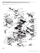
INSULATED JACKET INSTALLATION INSTRUCTIONS
IMPORTANT: Before you build the frame, you must take into consideration the total weight
of the liner, grill and any finishing materials.
A
B
C
D
E
F
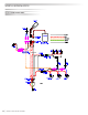
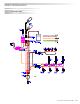
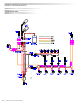
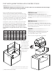
4” square holes for
gas and electrial
connections both
left and right sides
(rear or bottom
access). Make these
holes in the frame
based on your
requirements.
1” Screws can be provided to help straighten out the
sides of the LIJ if necessary. Contact Lynx for details.
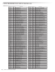
Refer to the table below for the proper framing
dimensions for the insulation jacket. Determine the entry
point for both the gas inlet and electricl connections. Make
the 4” square holes for gas and electrical connections (rear
or bottom access) based on your requrements. Note that
the electrical connections are located on the left side and
the gas connections are located on the right side.
A Carpenter’s “spirit level” should be used to assure that
the framing is level, both front to back and side to side.
Note: Never under any circumstance should you install
the transformer, run wiring or run a quick disconnect
hose inbetween the grill and the inside of the insulating
jacket.
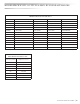
Model A B C D E F
LIJ27
33 5 23 ¾ 4 ½ 3 11 5/8
LIJ30
36 5 26 ½ 4 ½ 3 11 5/8
LIJ36
42 5 23 ¾ 4 ½ 3 11 5/8
LIJ42
48 5 26 ½ 4 ½ 3 11 5/8
LIJ54
60 5 26 ½ 4 ½ 3 11 5/8
LINER INSTALLATION
Posititon the liner into the frame. No part of the
combustible enclosure can protrude above the top surface
or in front of the face surface of the liner. Shim the liner if
necessary.
GRILL INSTALLATION
Use the proper equipment to support the grill. Place the
grill into the liner and engage it over the liner lip across the
back and sides. The liner is designed to support the grill
without additional fasteners.
FINISHING
If desired any gap remainng between the liner and
the combustible enclosure may be filled with a
non-combustilble sealant or caulk.
Note: for service the grill must be removable.