
Vent Hood Installation


Page 4 of 4 P/N 11864.00 Rev A
1
2
3
4 4
3
2
1
N
Receptacle
Plug
G L1
18 B #12
18 G #11
18 W #13
18 W #25
18 B #24
18 BL #23
18 R #22
18 W # 15
12 B #1
18 R #4
18 BL #3
18 B #2
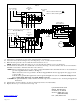
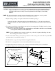
FIG - 6
1. Remove Shaded Twist Ons
2. Remove Wires At Receptacle
N G L1
18 R #4
18 W # 15
12 W #13
12 B #1
18 G #11
12 B #12
18 B #2
18 BL #3
44
2
3 3
2
1 1
White
Black
Blue
Red
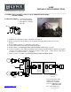
Remote Blower
Junction Box
Conduit
Receptacle
Hood
Box
Power Supply
Capacitor
Yellow
Yellow
Motor
Green
Change #12 & #13 TO 12GA Wire (Supplied)
Model LOHE Only
Receptacle
Hood
Box
Power Supply
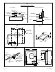
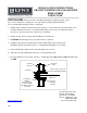
A. Access the hood junction box, remove the designated twist on connectors.
B. Access the remote blower wiring box by removing the top cover, set aside screws for later use.
C. Run four wires per local code, in conduit from remote blower to hood.
NOTE: maintain white, black, blue and red color code from blower wiring box to hood connections.
D. Connect 4-wire from blower to hood with twist-on connectors from step – A; remote white to #13 & 15, remote black to
#24 black, remote blue to #23 blue and remote red to #22 red.
NOTE: When connecting the hood to power supply, replace the black #12 wire and white #13 wire on hood with the 12
ga. wires supplied with the ventilator. See Fig – 6.
When remote blower is to be grounded to the Power Supply Main Ground use appropriate wire gage per local
codes. See Fig – 6.
If the blower is grounded through the Hood the 16 ga Green Pigtail wire at the hood Must Be Changed to 12
Ga, or Appropriate Wire Gage to Comply With Local Codes.
CAUTION: To prevent malfunction and/or harm to electrical components, connections are to be made per diagram and
instructions.
E. Check rotation of blower wheel to be sure it rotates freely and does not rub brackets.
F. Replace blower top cover and screws from step – B.
Lynx Professional Grills
6023 E. Bandini Blvd.
Commerce, CA 90040
Service: (888) Buy-Lynx
(888-289-5969)
www.lynxgrills.comwww.lynxgrills.com Fax: (323) 838-1778