User Manual Please Note: The LT-MADI requires your Aurora converter to have Firmware Version 24 or later. Any Aurora shipped from Lynx Studio Technology prior to September 9th, 2009 will have previous firmware installed in it. For information about updating the Aurora’s firmware to a compatible revision, see Section 3.3 Operation Requirements. Lynx Studio Technology, Inc. www.lynxstudio.com support@lynxstudio.
User Manual Table of Contents 1 2 3 Introduction............................................................................................................................. 1 Features ................................................................................................................................... 1 Before You Begin ................................................................................................................... 2 3.1 Contents ............................................
1 Introduction Thank you for purchasing the LT-MADI™! We are proud to provide you with a reliable, professional-quality product for your digital audio requirements. This manual provides basic information to help you get started. Additional information is available via our web site and email support. Please refer to Section 12, Support, at the end of this manual for support contact information.
3 Before You Begin We recommend that you read through the manual to acquire an overview of the installation procedure and use of the LT-MADI. This manual will presume a working knowledge of the Aurora converter. For additional information, please refer to the Aurora owner’s manual. 3.1 Contents Verify that you received the following in the LT-MADI shipping carton: • LT-MADI card in cushioned antistatic bag • Warranty Registration Card • Lynx Installation CD • 1/2” Standoff Post 3.
4 Nomenclature used in this manual The following typographic conventions are used in this manual: ¾ ALL UPPER CASE TEXT refers to a specific parameter selection control (i.e. SYNC SOURCE) or a cable connection. ¾ Text in quotation marks indicates a parameter selection value or menu option (i.e. “EXT”). ¾ Phrases, such as: Click Setups Mixer > About Aurora Remote…, use the greater than symbol (“>”) to indicate multiple menu options or mouse selections within a software control context.
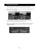
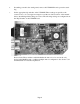
6 Installation Procedure 1. Remove the AC power cord and take the top off of the Aurora 16 or Aurora 8. There are seven large screws plus one small screw near the center of the front faceplate. 2. Before installing the LT-MADI card, slide switch 4 (labeled W4 on PCB) of SW1 to the OFF position (towards back panel) If you are updating an older Aurora that has jumper pins at JP6, instead of the W4 switches, please call Lynx Technical Support for instructions. 3.
4. Remove the screw from the Aurora circuit board that is adjacent to the JP1 connector and the white serial number/barcode label. Set the screw aside for reuse. 5. Install the standoff post (included with the LT-MADI) in this same hole.
6. Grounding yourself to the earth ground, remove the LT-MADI from its protective static bag. 7. Set the appropriate dip switches on the LT-MADI. These settings are specific to the context of use, so it is strongly encouraged to read the associated sections of the manual before determining which settings are correct.
Note that when the Aurora is the only MADI device connected, switch SW3 should be OFF and switches SW1 and SW 2 should be ON (this is the default state for a new LTMADI card). When multiple Auroras are used, each needs a unique device ID to be correctly integrated, and SW3 should be ON.
8. Set the JP2 jumper for the MADI 56 or 64 channel modes. MADI devices can utilize 56 channel operation or 64 channel operation. The LT-MADI inputs auto-detect the appropriate mode, but the outputs must be configured to work correctly with MADI devices receiving streams from the LT-MADI outputs. It is crucial to consult the documentation for your MADI equipment to determine which mode is appropriate. See MADI 56/64 Channel Modes. 64 channel mode is the LT-MADI default state. 9.
10. Secure LT-MADI with three screws; one on the standoff and two from the back panel of Aurora. Keep screws loose until LT-MADI is properly aligned, then tighten snugly, but do not overtighten. 11. Reinstall the Aurora lid using the eight screws that had been removed. Do not over tighten the small screw near the center of the front faceplate as it is easily damaged. 12. Plug in and power up the Aurora using the front panel standby switch. You can see the LT-MADI from the slits in the Aurora lid.
7 External Connections MADI (Multichannel Audio Digital Interface), also known as AES10, is an AES approved digital audio standard. Originally conceived for use with Digital Consoles, MADI has since expanded into other audio contexts where high channel count audio transfers are required, such as broadcast, installations, live sound, video post-production, etc. MADI is distinct from other common digital audio standards by the number of channels supported per cable connection.
64-channel mode is the default. If this is a new installation and your connected hardware supports 64-channel mode, then no changes are required. Maximum channel count is also dependent on the operating sample rate. In 56-channel mode, the LT-MADI is capable of 56 channels at 44.1kHz or 48kHz sample rates, 28 channels at 88.2 or 96kHz and 14 channels at 176.4 or 192kHz. In 64-channel mode, the LT-MADI is capable of 64 channels at 44.1kHz or 48kHz sample rates, 32 channels at 88.
7.2 LT-MADI 16/32-channel modes When used with some LSLOT expansion cards like the LT-MADI, an Aurora 16 can be configured to operate as a 16-channel or a 32-channel device, depending on your ultimate I/O needs. 16-channel mode is ideal for streaming audio via MADI to the Auroras Analog I/O OR AES I/O, but not both. In contrast, 32-channel mode provides access to all AES/EBU and ANALOG channels on the Aurora, simultaneously and independently. 7.2.
7.2.3 Switching and verifying mode Switching between 16-channel and 32-channel mode is done by holding down the TO ANALOG OUT button on the Aurora front panel for one-half second. All of the Aurora LEDs will flash to confirm the switch has occurred. There are two ways to confirm that a unit is in 16-channel or 32-channel mode: 1. Run the Aurora Remote Control software via MIDI.
7.3 Connector Types MADI is typically carried on one of two connector and cable types, and both are supported by the LT-MADI card. The older, original method is coaxial cable with BNC connectors. The LTMADI requires 75 Ohm coaxial cable. Cables of this sort are inexpensive and easily procurable. The alternative, more typical with newer MADI devices, uses SC-Type Optical connections with network fiber optic cables.
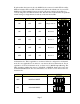
With this number of influential factors, there are a significant number of possible combinations. A key element to multi-Aurora configurations is correctly setting the Unit ID switch on each LTMADI card. 7.4.1 Unit ID Switch When multiple Auroras are daisy chained via MADI, it is essential that they each occupy unique positions in the MADI stream. MADI is a serial medium, so devices in a MADI daisy chain will be mounted in a sequential fashion.
Back of Aurora ON ON OFF ON C&K SDA04 Device 2 1 2 3 4 Back of Aurora ON OFF OFF ON C&K SDA04 Device 3 1 2 3 4 The factory default state of these Switches is for Single Aurora operation. 7.4.2 Delay Compensation Each device in a MADI chain operates a number of samples behind or ahead of the previous device, due to latencies intrinsic to the transportation of MADI data through the daisy-chain.
In a system where there is a MADI device that is both the signal source and final destination, connected devices form a loop with outputs connected to inputs through each device in the chain. The example below shows two Aurora 16s connected to a MADI source/destination: In the case of a system when the MADI source and destination are different devices, the configuration would look like this: Alternatively, it is possible to have the MADI stream only move in one direction.
7.4.5.1 32-channels of Analog I/O, No AES For this configuration you will need two Aurora 16s. The first Aurora in the chain should be configured as Device 0 and the second as Device 1. Only the Analog I/O on the Aurora will be connected to signal sources and destinations. 16/32 channel mode Active Active Active Channels Channels Channels 44.1/48kHz 88.2/96kHz 176.
7.4.5.3 32 Channels of Analog I/O AND 32 Channels of Digital I/O For this configuration you will need two Aurora 16s. They should be configured, in order, as Devices 0 – 1. All Analog I/O and AES/EBU on both Auroras will be connected to signal sources and destinations. 16/32 channel mode Aurora 16 - Device 0 Aurora 16 Device 1 7.4.5.4 Active Active Active Channels Channels Channels 44.1/48kHz 88.2/96kHz 176.
The table below details SYNC SOURCE choices for the Aurora as pertinent to use within a MADI-based system. Please see section 2.4 of the Aurora manual for general information about available clock settings and clocking considerations with the Aurora. EXT - External Clock signals from Aurora WORD CLOCK input. In general, WORD CLOCK is the preferred means to clock devices (including multiple Auroras) in a MADI system. Auroras can be daisy-chained via wordclock, or recipients of wordclock distribution.
9 Routing and Channel Mapping Sending audio signals into and out of the LT-MADI is straightforward. Routing can be initiated globally from the Aurora front panel or on a per-channel basis by using the Aurora Remote Control software. 9.1 Routing Logic The LT-MADI card implements a routing scheme whereby signals sent to Analog or Digital inputs on the Aurora get automatically routed to appropriate MADI Outputs. Signals going into MADI Inputs however can be routed to the AES, Analog or MADI Outputs.
9.1.2 Input Routing Signals from MADI inputs can be routed to Aurora Analog and/or AES/EBU Outputs. The Aurora will need to be configured for this routing scheme and will not operate this way in its default state. Input routing can be set globally from the Aurora Remote Control software or from the Aurora front panel. Additionally, input routing can also be initiated by the user on a per-channel basis with the Aurora Remote Control software. 9.1.2.
9.1.2.2 Per Channel Routing In addition to global routing, an LT-MADI equipped Aurora is capable of routing MADI streams to Aurora Analog and Digital outputs on a per-channel basis. MADI streams can also be duplicated across multiple Aurora outputs. For instance, MADI input 1 and 2 can be routed to Analog outputs 7 and 8, while MADI inputs 3 and 4 can be routed to Analog outputs 5 and 6 AND Digital out 1 and 2 at the same time.
I/O & Settings” page. The Aurora is capable of two sources per output at any sample rate. LSLOT sources will represent MADI signals when an LT-MADI card is installed. The features on the Output section of the “Analog I/O” page are described below: q These indicators will illuminate when three consecutive full-scale samples are detected on the Aurora Analog inputs and outputs or when a summing overrun occurs on the Aurora Analog outputs. The indicator will remain illuminated for 250ms.
and Source B) can be established for each output. For these custom monitor sources to be active, the TO ANALOG OUT switch on the Digital I/O & Settings page must be set to “Remote”. In this state all three LEDs for the TO ANALOG OUT button on the Aurora front panel will be illuminated. t These buttons allow individual monitor sources to be selected for each analog output when using Remote Routing. Clicking a button allows selection of any Analog, Digital or LSLOT input source (LSLOT = MADI).
10 Updating the firmware on the LT-MADI Updating the firmware on the LT-MADI uses the same process as updating the firmware on the Aurora. With the most current Aurora Firmware Update program, a properly installed LT-MADI can be selected as the device to program. Instructions for downloading and running the Aurora Update program for Windows or OSX are available at: www.lynxstudio.com > Support > Downloads > Product = Aurora.
11 Specifications MADI PORTS Type Coaxial input and output / fiber optic input and output Channels In 56 Channel Mode: 56 channels @ 48kHz 28 channels @ 96kHz 14 channels @ 192kHz In 64 Channel Mode: 64 channels @ 48kHz 32 channels @ 96kHz 16 channels @ 192kHz CLOCK SYNCHRONIZATION Clock Sources MADI or Aurora slave ARCHITECTURE Core FPGA-based core. Support for firmware field upgrades. CONNECTIONS I/O Ports (2) Bracket-mounted BNC connectors. (2) Bracket-mounted fiber optic SC connectors.
12 Support We are devoted to making your experience with the LT-MADI trouble-free and productive. If the operational sections of this manual did not help resolve your questions, several support options are available to you: 12.1 Lynx Website Support Resources Logging on to http://www.lynxstudio.com/support.
13 Warranty Information One year Free Labor / One year Parts Exchange This product must be returned to the factory for repair. Who Is Covered? You must have proof of purchase to receive warranty service. A sales receipt or other document showing when and where you purchased the product is considered proof of purchase. This warranty is enforceable only by the original retail purchaser.