Installation and Users Guide Lynx Studio Technology, Inc. support@lynxstudio.
Page 2
Contents Introduction ............................................................................................................. 4 Before you begin ................................................................................................ 4 Manual Conventions ........................................................................................... 5 Warranty Registration ......................................................................................... 5 Windows 95/98® Installation .......
Introduction Introduction Thank you for purchasing the LynxONE™! We are proud to provide you with a reliable, professional quality product for your digital audio and MIDI needs. This Installation and Users Guide provides basic information to help you get started. Before you begin Before you begin the installation of your LynxONE card, we recommend that you read through the Installation and Users Guide to acquire an overview of the installation procedure and use of the LynxONE.
Introduction Manual Conventions This manual uses the following typographic conventions: • Underlined text denotes characters that are to be typed using the keyboard. • ALL UPPER CASE text denotes the names of specific connectors. • First Character Upper Case text denotes LynxONE Mixer control names or menu options. • Italic text denotes emphasis or a warning.
Installation Windows 95/98/98SE® Installation The procedure for installing the LynxONE in Windows 95/98/98SE requires that the LynxONE Setup Program be run before you install your LynxONE inside your computer. This program will install the required driver files needed for the Windows Plug-andPlay configuration manager to recognize the LynxONE as a new device and will install the LynxONE Mixer application. Running Setup 1. 2. 3. 4. 5. 6. 7.
Installation Windows NT® Installation The procedure for installing the LynxONE in Windows NT requires that you install your LynxONE inside your computer before the LynxONE Setup Program is run. This program will install all the required driver files and the LynxONE Mixer application as well as configure your system to recognize the LynxONE. Installing the LynxONE 1. 2. 3. 4. 5. 6. 7. 8. 9. Turn OFF the power to your computer system and disconnect the power cords.
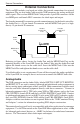
External Connections External Connections The LynxONE includes two break-out cables that provide connections for external equipment. The six-foot Audio Cable provides XLR connectors for analog and digital audio signals. The two-foot MIDI/Clock Cable provides 5-pin DIN connectors for the two MIDI ports and female BNC connectors for clock input and output.
External Connections Please note that with 16 dB of headroom, the LynxONE’s analog outputs are capable of delivering +20 dBu signal levels. It is important to verify that the equipment you are driving is capable of handling these signal levels in order to prevent clipping or possible damage. Digital Audio The XLR connectors on the Audio Cable, labeled DIGITAL IN and DIGITAL OUT are used for AES/EBU and S/PDIF digital audio connections.
Using Your LynxONE Using Your LynxONE With the LynxONE and its drivers properly installed in your computer, you can begin to use its capabilities with any third party audio or MIDI application running under Windows. In order for these applications to access the LynxONE you must select one of the LynxONE audio or MIDI devices in an application’s configuration menu for audio, wave or MIDI devices. Refer to the “Working with Third Party Applications” section for more information regarding device selection.
Using Your LynxONE Mixer Configuration Recall The state of the Mixer settings are saved each time Windows is shut down. The stored settings are automatically recalled the next time Windows is restated. Clock Source Requirements A valid clock source signal must be connected to the appropriate LynxONE clock connector when the Sample Clock Source is set to either Digital, External, or Header. If a signal is not present, the sample clock generator will run very slow or erratically.
Using Your LynxONE Quick Audio Test The installation of your LynxONE can be tested using the LynxONE Mixer and the Sound Recorder application that ships with Windows 95/98 and Windows NT. Any other audio application capable of audio recording and playback can be used in a similar manner. 1. Connect a stereo analog signal source to the LEFT IN and RIGHT IN connectors on the Audio cable. 2.
Mixer Reference Mixer Reference The LynxONE Mixer provides complete software control of the audio features of the LynxONE and an indication of signal level during recording and playback. This section describes the function of each menu and control of the mixer. Mixer Menu With one LynxONE installed in your computer the first selection in the Mixer Menu will be “LynxONE Mixer” proceeded by a check mark.
Mixer Reference Record Dither – Enables the addition of dither during recording of 8-bit or 16-bit files or when the record Volume Fader is set below full-scale. Dither is not added to the signal for 24-bit or 32-bit files when the Volume Fader is at full-scale. Play Dither – Enables the addition of dither during recording of 8-bit or 16-bit files or when the record Volume Fader is set below full-scale. Dither is not added to the signal for 24-bit or 32-bit files when the Volume Fader is at full-scale.
Mixer Reference Digital Input Status – Just below the Volume Faders on the Digital In panel are two status indicators. The top indicator delineates professional or consumer channel status with PRO or CON labels. Professional status is generally associated with an AES/EBU signal, and consumer status is generally associated with an S/P DIF signal.
Mixer Reference Auto – Automatic selection. Valid for Internal and Digital clock sources. 13.5MHz – 13.5MHz video dot clock. Valid for External and Header clock sources. 27MHz – 27MHz video dot clock. Valid for External and Header clock sources. Word – Word clock. Valid for External and Header clock sources. Word256 – 256 times word clock. Valid for External and Header clock sources. Rate – Displays the current sample clock rate of the LynxONE.
Working with Third Party Applications Working with Third Party Applications Compatibility The drivers included with your LynxONE provide compatibility with all standard third party audio editing and MIDI sequencing applications that communicate with Windows Wave audio, DirectSound and MIDI devices. A list of applications that have been tested for compatibility will be provided on the Lynx web site in the near future.
Working with Third Party Applications Audio I/O Selection The selection of a desired audio input or output is accomplished by choosing the associated audio device name in an application. Each device name is associated with a connection on the LynxONE Audio cable, as listed in the table below. Using the table, make the desired signal connections to the LynxONE Audio Cable and select the appropriate audio device in your application.
Working with Third Party Applications In order to generate an audio file with the correct sample rate stored in its header, the sample rate specified for the recorded file must match the sample rate of the equipment driving the digital input. Failure to do so will cause subsequent playback of the recorded file at the wrong sample rate.
Configuring Multiple LynxONE’s Configuring Multiple LynxONE’s Up to four LynxONE cards can be installed in a computer for additional audio and MIDI channels. If required, all LynxONE’s in a computer can be configured to maintain sample accurate synchronization during digital audio recording and playback. Cards are synchronized in a master-slave arrangement. One card is selected as the master which provides the word clock source for the other slave cards in the system.
Configuring Multiple LynxONE’s 4. 5. Listen to the playback of any wave file and note which LynxONE card is generating the audio signal. In this case, the card generating audio is adapter 1. Repeat steps 3 and 4, for “LynxONE 2 Analog Output”, “LynxONE 3 Analog Output”, and so on until all LynxONE’s in your system have been identified. The next step is to choose which LynxONE will act as a master.
Troubleshooting Troubleshooting When Windows starts I see a LynxONE Mixer error - “No mixer device drivers are available”. This error will appear when the LynxONE Mixer is loading during Windows startup and the LynxONE is not installed correctly. You should check the following items: 1. With the computer power off, verify that the card is properly seated in the PCI slot. 2. Verify the LynxONE’s resources are not conflicting with some other device in your system.
Troubleshooting I cannot record from the LynxONE’s digital input. The LynxONE Digital Input device must be configured as the record device in your application. Select this device in the audio or wave device configuration menu. With the device properly set, the meters in the LynxONE mixer will indicate the digital input signal level while recording. See “Working with Third Party Applications” for more information. There is no signal on the digital output during playback.
Troubleshooting When I connect the LynxONE analog outputs to the MIC inputs on my Mackie mixer I hear distortion. The MIC inputs are being overdriven. Even with the mic gain adjusted to its lowest setting, the maximum signal level that the MIC inputs of the smaller Mackie mixers can handle is +14 dBu. In the +4 dBu trim setting, the LynxONE is capable of delivering a +20 dBu signal. To solve this problem use 1/4” line inputs of the mixer.
Support Why don't I hear anything when I play a MIDI file? The LynxONE has two MIDI ports (2 in & 2 out) which can be connected to external MIDI hardware. To play a MIDI file you must have an external synthesizer connected to one of the MIDI outputs, and that synthesizer must have it's audio output connected to your amplifier/speakers or to headphones. The LynxONE has no on-board synthesizer.
Appendix Appendix Specifications Analog I/O Number / Type Level Input Impedance Output Impedance Output Drive Capability A/D and D/A Type Sample Rates Bit Depth On-board Buffer Size Analog Performance Frequency Response Dynamic Range Signal-to-Noise Channel Crosstalk Input THD+N Output THD+N Two inputs and two outputs / cross-coupled electronically balanced or unbalanced, XLR connectors on Audio cable +4 dBu nominal /+20dBu max. or –10dBV nominal / +6dBV max.
Appendix General PCI Bus Power Size Shipping Weight Certifications Version 2.1 compliant, Transfer rate: up to 132 Mbytes/sec +5V @ 400 mA, +12V @ 220 mA, -12V @ 95 mA 5.0” H X 7.4” W X 0.75” D (half-size PCI card) 2.7 lbs.
Appendix XLR Connector Wiring and Adapters This section describes the proper wiring of cables that can be used to adapt both the analog and digital audio XLR connectors on the LynxONE Audio Cable.
Appendix The wiring method for unbalanced connections with XLR connectors to RCA/Phono phone connectors using shielded twisted pair cable (2 wire + shield) is as follows: XLR Pin 1 (GND) to cable shield with no connection on the other end XLR Pin 2 (+) to signal wire and to the Phono center pin XLR Pin 3 (-) to the other signal wire and to the Phono sleeve Unbalanced Connections with Single Conductor Cable In some cases it may be necessary to use single-conductor cable to adapt to unbalanced devices.
Appendix The wiring method for unbalanced connections with XLR connectors to unbalanced RCA/Phono phone connectors using coaxial cable (1 wire + shield) is as follows: XLR Pin 1 (GND) no connection XLR Pin 2 (+) to signal wire and to the Phono center pin XLR Pin 3 (-) to the cable shield and to the Phono sleeve Page 30
Appendix Connector Pinouts Audio Port The Audio Port is a female 25-pin D-connector with the following connections: Pin Signal Pin Signal 1 2 3 4 5 6 7 8 9 10 11 12 13 Digital O ut Hot Digital O ut Gnd Digital In Cold none none none Right O ut Hot Right O ut Gnd Right In Cold Left O ut Hot Left O ut Gnd Left In Cold none 14 15 16 17 18 19 20 21 22 23 24 25 Digital O ut Cold Digital In Hot Digital In Gnd none none none Right O ut Cold Right In Hot Right In Gnd Left O ut Cold Left In Hot Left In Gnd
Appendix Instructions to the User This equipment has been tested and found to comply with the limits for a class B digital device, pursuant to part 15 of the FCC Rules. These limits are designed to provide reasonable protection against harmful interference in a residential installation. This equipment generates, uses and can radiate radio frequency energy and if not installed and used in accordance with the instructions, may cause harmful interference to radio communications.
Appendix EMC Certifications FCC DECLARATION OF CONFORMITY TRADE NAME: MODEL NUMBER: COMPLIANCE TEST REPORT NUMBER: COMPLIANCE TEST REPORT DATE: RESPONSIBLE PARTY (IN USA): ADDRESS: TELEPHONE: Computer Audio Card LynxONE B80812D1 August 12, 1998 Lynx Studio Technology, Inc. 1048 Irvine Ave, PMB 468, Newport Beach, CA 92660 (949) 515-8265 This equipment has been tested and found to comply with the limits for a Class B digital device, pursuant to Part 15 of the FCC rules.
License Agreement This legal document is an agreement between you and Lynx Studio Technology, Inc. By opening the sealed board package, or written materials, you are agreeing to become bound by the terms of the agreement, which includes this License and Limited Warranty (collectively the “Agreement”). This Agreement constitutes the complete agreement between you and Lynx Studio Technology, Inc. If you do no agree to the terms of the Agreement, DO NOT OPEN the anti-static bag containing the LynxONE board.
Page 35