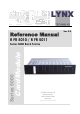
Reference Manual R FR 5010 / R FR 5011 Series 5000 CardModule Series 5000 Rack Frame © LYNX Technik AG Brunnenweg 3 64331 Weiterstadt Germany www.lynx-technik.com Ver 2.
Reference Manual R FR 5010 Version1.4 Information in this document is subject to change without notice. No part of this document may be reproduced or transmitted in any form or by any means, electronic or mechanical for any purpose, without express written permission of LYNX Technik AG. LYNX Technik AG may have patents, patent applications, trademarks, copyrights or other intellectual property rights covering the subject matter in this document.
Reference Manual R FR 5010 Version1.4 WARNING Electrical supplies in excess of 50 (fifty) volts peak value are potentially hazardous or lethal. AC supplies between 100 and 250 peak volts exist within the rack frame chassis when connected to AC power. Only qualified personnel should service the rack frame assembly. Removal of technical earth may render the equipment dangerous and intentional removal is prohibited. This unit has to be separated from mains by disconnecting the power supply cords.
Reference Manual R FR 5010 Version1.4 WARNUNG! Wenn das Gerät an das Wechselstromnetz angeschlossen ist, treten innerhalb des Gerätes Wechselspannungen zwischen 100 und 250 V auf, die potentiell gefährlich oder tödlich sein können. Deshalb darf Reparatur und Instandhaltung nur von qualifiziertem Personal durchgeführt werden. Das Entfernen des Schutzleiters kann das Gerät in einen gefährlichen Zustand bringen, vorsätzliches Entfernen des Schutzleiters ist verboten.
Reference Manual R FR 5010 Version1.
Reference Manual R FR 5010 Version1.4 Warranty LYNX Technik AG warrants that the product will be free from defects in materials and workmanship for a period of two (2) years from the date of shipment. If this product proves defective during the warranty period, LYNX Technik AG at its option will either repair the defective product without charge for parts and labor, or will provide a replacement in exchange for the defective product.
Reference Manual R FR 5010 Version1.4 Regulatory information Europe Declaration of Conformity We LYNX Technik AG Brunnenweg 3 D-64331 Weiterstadt Germany Declare under our sole responsibility that the product TYPE: R FR 5010 / R FR 5011 To which this declaration relates is in conformity with the following standards (Environments E1-E3): EN 55103-1 /1996 EN 55103-2 /1996 EN 60950 /2001 following the provisions of 89/336/EEC and 73/23/EEC directives.
Reference Manual R FR 5010 Version1.4 Contents Warranty................................................................................... 6 Regulatory information ........................................................... 7 Europe .............................................................................................. 7 Declaration of Conformity........................................................... 7 USA...........................................................................................
Reference Manual R FR 5010 Version1.4 Electrical Installation. ............................................................ 31 Installation Instructions .......................................................... 32 Installations-Anweisung ........................................................ 33 Settings and Control .............................................................. 34 Specifications (R FR 5010 / R FR 5011).................................. 35 Available Options ...............................
Reference Manual R FR 5010 Version1.4 Getting Started Packaging The shipping carton and packaging materials provide protection for the module during transit. Please retain the shipping cartons in case subsequent shipping of the product becomes necessary. Product Description The R FR 5010 / R FR 5011 is a high quality 2 RU high 19 inch rack frame enclosure for the LYNX Series 5000 CardModules, designed primarily for broadcast and professional applications.
Reference Manual R FR 5010 Version1.4 board multifunction LED has various states to indicate different alarm conditions and a separate GPO alarm output is provided for connection to an external monitoring system. The system is convection cooled plus forced aircooling (low noise fans) so it can be used in areas where noise level is critical. Power supplies have a small temperature controlled DC micro fan, which is only used when needed and is also low-noise when operating.
Reference Manual R FR 5010 Version1.4 Rack Layout Figure 2 and 3 shows exploded views of the R FR 5010 / R FR 5011. The Front cover is removed and not shown. Caution : Do not obstruct ventialtion holes on top and bottom sides of rack. Refer to mounting instructions for more details. Mounting rails on rear of rack for connection panels Mid Rack Vertical Support CardModule Figure 2.
Reference Manual R FR 5010 Version1.4 Caution : Do not obstruct ventilation holes on top and bottom sides of rack. Refer to mounting instructions for more details. Controller Mid Rack Vertical Support CardModule Rack mounting Screws Note. Exploded views are shown for reference only It is not necessary to disassemble the rack as shown Figure 3 – Exploded rack view For clarity (to show rack construction) power supplies, rear termination panel and connection panels for the modules have been omitted.
Reference Manual R FR 5010 Version1.4 Power Supply The R FR 5010 / R FR 5011 includes the primary power supply. A second identical power supply can be added for redundancy. The Power supply is a sophisticated design designed for critical applications and includes power filtering and integral microprocessor. This monitors the supply operation and reports into the control system. Should a fault develop, the errors are alarmed in the following ways: • Via the LED located on the front of the supply (Figure 4).
Reference Manual R FR 5010 Version1.
Reference Manual R FR 5010 Version1.4 Rear Termination Panel The R FR 5010/ R FR 5011 has an integral termination panel on the rear of the rack for the connection of power and various other connections for expansion and interfacing. Figure 5 Figure 5 Rear Panel Connections Rack Connections Power Connection There are two power connections provided for the rack. One is for primary power and the other for the optional redundant power supply. Input power range is 100 to 240VAC 50 to 60Hz.
Reference Manual R FR 5010 Version1.4 A stud is provided on the termination panel for the connection of an external ground. (Figure 5) Note: the chassis is permanently grounded via the AC connections. ! ! Caution Service to be performed by qualified personnel only Caution Please remove power before attempting to exchange a power fuse. Only replace the fuse with a correctly rated replacement. For safety DO NOT physically disconnect or isolate the rack from earth for any reason.
Reference Manual R FR 5010 Version1.4 Alarm Function This function requires the controller option. The user can assign triggers for the preferred Major / Minor and No Alarm conditions using the controller and supplied software. The alarm connector provides GPO contacts for 2 alarm levels and a GPI input for future use. This allows for the connection of an external monitoring system.
Reference Manual R FR 5010 Version1.4 Extend Connection Bus Extension. This connection is used to interface racks together when using the optional LYNX control system. This is a simple (and inexpensive) way to extend the reach of the host RCT 5020 controller into several more racks fitted with RCT 5010 bus expanders. It uses a proprietary LYNX control interface and this connection is physically daisy chained between all connected racks. Connection details can be seen in the table below.
Reference Manual R FR 5010 Version1.4 Control Connection An external Control Interface is provided on the rear termination panel. When an R CT 5020 Rack Controller (or R CT 5030 Master Controller) is fitted to the rack this port can be used for two primary functions: 1. When configured as a RS 232 serial port this can be connected directly to a PC running the LYNX control software. 2.
Reference Manual R FR 5010 Version1.4 5 6 1 9 Figure 8. Control Connector LAN Connection This is a standard RJ48 connection and is used to provide standard TCP/IP network control connectivity into a control system. To be operational this port requires the R CT 5030 Master Controller is fitted to the rack.
Reference Manual R FR 5010 Version1.4 Alarm/LED Status Indicators There are a number of status / alarm indicators visible through the front panel of the R FR 5010 Rack frame. Figure 9. Figure 9.
Reference Manual R FR 5010 Version1.4 Power Supply LED Indicators The Table below shows the error conditions for the LED on the power supply units.
Reference Manual R FR 5010 Version1.4 Rack Configuration Assembly If starting with an empty R FR 5010 / R FR 5011 rack frame please follow the following steps for correct installation of the Series 5000 Card Modules Rack Layout Considerations If you have a variety of module types it’s a good idea to plan the order in which you install the various CardModules.
Reference Manual R FR 5010 Version1.4 Redundant Power Supply The basic RFR 5010 / R FR 5011 is supplied with the primary power supply installed. The redundant supply (option) is installed next to the primary supply. Remote Controller Depending on your system design you may have one of the LYNX controller options available (RCT 5010, R CT 5020 or R CT 5030). Install the controller into the first module slot next to the power supply(s).
OUT 2.4 OUT 2.3 OUT 2.2 OUT 2.1 SDI IN 2 OUT 1.4 OUT 1.3 OUT 1.2 OUT 1.1 SDI IN 1 OUT 2.4 OUT 2.3 OUT 2.2 OUT 2.1 SDI IN 2 D VD 3320 OUT 1.4 OUT 1.3 OUT 1.2 OUT 1.1 SDI IN 1 OUT 2.4 OUT 2.3 OUT 2.2 OUT 1.4 OUT 1.3 OUT 1.2 OUT 1.1 SDI IN 1 OUT 2.4 OUT 2.3 OUT 2.2 OUT 2.
Reference Manual R FR 5010 Version1.4 Hot Swapping Power Supplies The Series 5000 CardModules and Power Supplies are fully hot swappable in the event of a fault or failure. Power Supply Failure A failure in the Primary power supply will automatically trigger the use of the redundant supply (if fitted) and will trigger the following alarm conditions / indications(requires controller option).
Reference Manual R FR 5010 Version1.4 Rack Installation If you have an empty R FR 5010 rack frame we recommend you assemble the connection plates and modules as well as any options such as the redundant power supply and controller before mounting the Rack Frame into a 19” inch rack. (Please refer to assembly section) Location The R FR 5010 Rack frame can be located anywhere there is available 19-inch rack space. The rack will take up 2 Rack Units (RU) of vertical rack space.
Reference Manual R FR 5010 Version1.4 5101 rack frame may (due to the small airflow gap) restrict the flow of air to this piece of equipment. Also do not place equipment or objects on top of the R FR 5010 rack frame that could restrict airflow from the top of the rack. This may cause malfunction and damage due to excessive heat buildup. Mechanical Installation The R FR 5010 / R FR 5011 is secured into a standard 19-inch rack using 4 standard rack screws.
Reference Manual R FR 5010 Version1.4 Fig.11: Sub D 9 Connector on Front Cover of R FR 5011 Fig.
Reference Manual R FR 5010 Version1.4 Electrical Installation. Electrical power is connected to the R FR 5010 / R FR 5011 chassis via the two IEC power connectors located on the termination panel on the rear of the rack. There is no power switch provided. Two separate and isolated power connections are available, one for the primary power and one for the optional redundant power supply. Primary power is connected to AC in 1 ! ! Caution Please remove power before attempting to exchange a power fuse.
Reference Manual R FR 5010 Version1.4 Installation Instructions The rack frame chassis R FR 5010 / R FR 5011 is intended for operation in broadcast environments. The operation in excessive dust and moisture or extreme temperature requires special provisions like • dust filters • air conditioning • avoidance of condensed water. Caution! The power cords must meet the safety requirements of the country where the rack frame is used and has to be approved in this country, e.g.
Reference Manual R FR 5010 Version1.4 Installations-Anweisung Das Gerät R FR 5010 / R FR 5011 ist für Anwendungen in Fernsehstudios vorgesehen. Der Einsatz in erhöhter staubiger und feuchter Umgebung oder außergewöhnlichen Temperaturen erfordert besondere Maßnahmen wie • Klimatisierung • Staubfilter • Vermeiden von Kondenswasser. Die Netzkabel müssen den Sicherheits-Anforderungen in dem Land entsprechen in dem das Gerät verwendet werden soll und in dem Land zugelassen sein, z.B.
Reference Manual R FR 5010 Version1.4 Settings and Control There are no specific setting and control parameters for the card rack. This is provided via controller option (if fitted) and the individual CardModule assemblies. Please refer to the reference manuals supplied with these items for details on specific settings and controls available.
Reference Manual R FR 5010 Version1.4 Specifications (R FR 5010 / R FR 5011) Mechanical Size Weight (empty) Connections 2 RU high x 32.5 cm deep including connectors and front cover. 31 cm without front cover. Standard 19” rack mount.
Reference Manual R FR 5010 Version1.4 Available Options Below is a list of available options for the R FR 5010 rack frame. Please refer to product brochures or our web site for more detailed information.
Reference Manual R FR 5010 Version1.4 Parts List There are no user serviceable electronic assemblies within the R FR 5010 module. The parts list below shows high-level sub assemblies used in this rack, which can be ordered separately for maintenance purposes. R FR 5010 Rack Frame (complete) Description Series 5000 Rack Frame Model Number R FR 5010 Part Number 6.155.001.000 Main sub assemblies Main term panel Part Number: 6.155.001.030 Front Cover Part Number: 6.155.001.
Reference Manual R FR 5010 Version1.4 Contact Information Please contact your local distributor; this is your local and fastest method for obtaining support and sales information. Lynx Technik can be contacted directly using the information below. Address LYNX Technik AG Brunnenweg 3 64331 Weiterstadt Germany Website www.lynx-technik.com E-Mail info@lynx-technik.
Reference Manual R FR 5010 Version1.