
Operating Instructions and Installation Instructions


Page 9
The nominal analog signal levels are compatible with either professional or consumer
equipment. Use the Trim controls on the LynxTWO Mixer application to select +4dBu
for balanced professional devices or –10dBV for balanced or unbalanced consumer
devices.
Please note that with 16 dB of headroom, the LynxTWO’s analog outputs are capable
of delivering +20 dBu signal levels. It is important to verify that the equipment you
are driving is capable of handling these signal levels in order to prevent clipping or
possible damage.
Digital Audio
The XLR connectors on the L2Sync Cable, labeled DIGITAL IN and DIGITAL OUT
are used for AES/EBU and S/P DIF digital audio connections. Connect AES/EBU
devices directly and select AES/EBU Digital Format in the LynxTWO mixer application.
Connect to S/P DIF devices using the supplied XLR-to-RCA adapters. Select S/P DIF
Digital Format in the LynxTWO mixer application.
LTC Connections
Two BNC connectors on the L2Sync Cable, labeled LTC IN and LTC OUT are used to
connect to the LynxTWO’s LTC reader and generator.
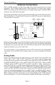
Sync Input and Clock Output Connectors
Two BNC connectors on the L2Sync Cable, labeled SYNC IN and CLOCK OUT are
used to synchronize the LynxTWO with external equipment. The connectors support
TTL or Composite Video level signals and should be connected with 75-ohm coaxial
cable. Connect the SYNC IN connector to the clock output or video output of an external
device and select External as the Sample Clock Source in the LynxTWO mixer. Adjust
the clock Reference to match the incoming clock type.
CLOCK OUT is a word clock that tracks the sample rate of the LynxTWO. Connect
this output to the word clock input of an external device.
Header Connectors
The Header connectors labeled CLOCK IN and CLOCK OUT are used to synchronize
the LynxTWO with equipment located inside your computer. For systems containing
multiple LynxTWO’s, these connectors are utilized to synchronize the sample clocks
of each card. The connectors support TTL level signals and should be connected using
the Lynx Internal Clock Cable, Lynx Universal Clock Cable or similar 75-ohm coaxial
cable.
Connect the CLOCK IN connector to the clock output of an internal device and select
Header as the clock source in the LynxTWO mixer. Adjust the clock Reference to
match the incoming clock type.
The signal on the CLOCK OUT header is a word clock that tracks the sample rate of
the LynxTWO. Connect this output to the word clock input of an internal device or
another LynxTWO.
External Connections