Biped BRAT Assembly Guide Safety first! Wear eye protection and never touch a powered robot! Important! To assemble the BRAT robot, construct a right leg (following the pictures on the right), and a left leg (by following the pictures on the left)! Keep in mind that the pictures marked "Right Leg" are the robot's right leg. After the legs are constructed, the images will no longer be split. Image of completed robot. Step 1. Attach a multi-purpose bracket to the foot as shown, using three 2-56 x .
Step 2. Attach the "L" bracket to a short "C" bracket as shown, using two 2-56 x .250" screws and 2-56 nuts each. 4x 4x Figure 2. (Left Leg) Figure 2. (Right Leg) Step 3. Attach a multi-purpose bracket to the "L" bracket as shown, using two 2-56 x .250" screws and 2-56 nuts each. 4x 4x Figure 3. (Left Leg) Figure 3. (Right Leg) Step 4. Attach the assembly from Step 3 to the multi-purpose bracket on the foot. See figure 4-1 for detailed information. Figure 4-1.
Figure 4. (Left Leg) Figure 4. (Right Leg) Step 5. Connect two short "C" brackets as shown, using two 2-56 x .250" screws and 2-56 nuts each. 4x 4x Figure 5. (Left Leg) Figure 5. (Right Leg) Step 6. Attach the "C" brackets to the leg assemblies as shown. See figure 6-1 for detailed information. Figure 6-1. Figure 6. (Left Leg) Figure 6.
Step 7. Attach a multi-purpose bracket to the "C" bracket as shown. See figure 7-1 for detailed information. Figure 7-1. Figure 7. (Left Leg) Figure 7. (Right Leg) Step 8. Attach the leg assembly from step 7 to the 3" U-Channel as shown, using three 2-56 x .250" screws and 2-56 nuts on each side. 6x Figure 8. (Left Leg) Step 9. Your assembly should look like the image so far. Note, in the image the robot is face down.
Figure 9. Step 10. Install the two ankle servos as shown, using the included 3mm hardware, two #2 tapping screws, and the diagram below. Note, your servos may be a little off. We will fix this in software later. 4x Figure 10. Step 11. Install the knee and hip servos as shown. Use the #2 tapping screws and the diagram below. 8x Figure 11.
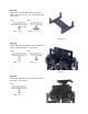
Step 12. Attach the 3/4" standoffs to the electronics carrier using four 4-40 x 1/4" hex socket head cap screws. 4x 4x Figure 12. Step 13. Attach the 5/16" standoffs to the U-Channel as shown, using two 2-56 x 1/4" screws. 2x 2x Figure 13. Step 14. Attach the electronics carrier as shown, using two 2-56 x 1/4" screws.
Figure 14. Step 15. To prevent the wires from tangling, you will want to secure them as shown. This can be done with wire ties or similar, not included. Make sure that the ankle servo is positioned as shown when securing the wires to ensure the full range of motion is available. Figure 15. Step 16. Attach the power switch to the electronics carrier as shown. Figure 16.
Step 17. Install the SSC-32 or Bot Board II using four 4-40 x 1/4" screws. Make sure to orient the board as shown. Connect the wiring harness to VS1 on the SSC-32 or VS on the Bot Board II as shown. Note, red is (+) and black is (-). If using a Bot Board II, go ahead and install the BASIC Atom Pro 28 chip as well. Atom Pro Orentation 4x Figure 17. Step 18. Connect the servos to their appropriate I/O channels on the board.
Step 19. Add the battery onto the U-Channel and secure it in place with zip-ties. Figure 19. Step 20. For controlling this robot with the just the SSC-32 and Sequencer, you can now move to the Sequencer tutorial. For those using a Bot Board II, you can now move on to the Autonomous, Water-Bottle Kicking, or PS2 tutorial. Figure 20.