The product information contained in this document is designed to provide general information and guidelines only and must not be used as an implied contract with Interlink Electronics, Inc. Acknowledging our policy of continual product development, we reserve the right to change, without notice, and detail in this publication.
FSR® Integration Guide & Evaluation Parts Catalog With Suggested Electrical Interfaces Force Sensing Resistors® – An Overview of the Technology ......................................................... Page 3 Force vs. Resistance.............................................................................................................. Page 3 Force vs. Conductance..........................................................................................................
Force Sensing Resistors An Overview of the Technology Force Sensing Resistors (FSR) are a polymer thick film (PTF) device which exhibits a decrease in resistance with an increase in the force applied to the active surface. Its force sensitivity is optimized for use in human touch control of electronic devices. FSRs are not a load cell or strain gauge, though they have similar properties. FSRs are not suitable for precision measurements. Force vs. Resistance The force vs.
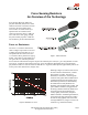
At the high force end of the dynamic range, the response deviates from the power-law behavior, and eventually saturates to a point where increases in force yield little or no decrease in resist-ance. Under these conditions of Figure 2, this saturation force is beyond 10 kg. The saturation point is more a function of pressure than force. The saturation pressure of a typical FSR is on the order of 100 to 200 psi.
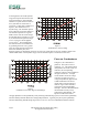
Figure 4 highlights the 0-1 kg (0-2.2 lbs) range of the conductance-force characteristic. As in Figure 3, the corresponding resistance values are included for reference. This range is common to human interface applications. Since the conductance response in this range is fairly linear, the force resolution will be uniform and data interpretation simplified. The typical part-to-part error band is also shown for this touch range.
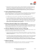
FSR Integration Notes A Step-by-Step Guide to Optimal Use For best results, follow these seven steps when beginning any new product design, proof-of-concept, technology evaluation, or first prototype implementation: 1. Start with Reasonable Expectations (Know Your Sensor) The FSR sensor is not a strain gauge, load cell or pressure transducer. While it can be used for dynamic measurement, only qualitative results are generally obtainable.
• Keep actuation cycle time consistent. Because of the time dependence of the FSR resistance to an applied force, it is important when characterizing the sensor system to assure that increasing loads (e.g. force ramps) are applied at consistent rates (cycle-to-cycle). Likewise, static force measurements must take into account FSR mechanical setting time. This time is dependent on the mechanics of actuation and the amount of force applied and is usually on the order of seconds. 4.
FSR Usage Tips The Do’s and Don’ts • Do follow the seven steps of the FSR Integration Guide. • Do, if possible, use a firm, flat and smooth mounting surface. • Do be careful if applying FSR devices to curved surfaces. Pre-loading of the device can occur as the two opposed layers are forced into contact by the bending tension. The device will still function, but the dynamic range may be reduced and resistance drift could occur.
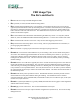
Evaluation Parts Descriptions and Dimensions Figure 5: Part No. 400 (0.2” Circle) Figure 6: Part No. 402 (0.5” Circle) Active Area: 0.5” [12.7] diameter Active Area: 0.2” [5.0] diameter Nominal Thickness: 0.012” [0.30 mm] Material Build: Semiconductive layer 0.004” [0.10] PES Spacer adhesive 0.002” [0.05] Acrylic Conductive layer 0.004” [0.10] PES Rear adhesive 0.002” [0.05] Acrylic Connector options a. No connector b. Solder Tabs (not shown) c. AMP Female connector Nominal thickness: 0.018” [0.
Active Area: 1.5” [38.1] x 1.5” [38.1] Nominal thickness: 0.018” [0.46 mm] Material Build: Semiconductive Layer 0.005” [0.13] Ultem Spacer Adhesive 0.006” [0.15] Acrylic Conductive Layer 0.005” [0.13] Ultem Rear Adhesive 0.002” [0.05] Acrylic Connectors a. No connector b. Solder Tabs (not shown) c. AMP Female connector Figure 7: Part No. 406 (1.5” Square) Dimensions in brackets: millimeters • Dimensional Tolerance: ± 0.015” [0.
Active Area: 24” [609.6] x 0.25” [6.3] Nominal thickness: 0.135” [0.34 mm] Material Build: Semiconductive Layer 0.004” [0.10] PES Spacer Adhesive 0.0035” [0.089] Acrylic Conductive Layer 0.004” [0.10] PES Rear Adhesive 0.002” [0.05] Acrylic Connectors a. No connector b. Solder Tabs (not shown) c. AMP Female connector Figure 8 Part No. 408 (24” Trimmable Strip) Dimensions in brackets: millimeters Dimensional Tolerance: ± 0.015” [0.
General FSR Characteristics These are typical parameters. The FSR is a custom device and can be made for use outside these characteristics. Consult Sales Engineering with your specific requirements. Simple FSR Devices and Arrays PARAMETER VALUE NOTES Size Range Max = 20” x 24” (51 x 61 cm) Min = 0.2” x 0.2” (0.5 x 0.5 cm) Any shape Device thickness 0.008” to 0.050” (0.20 to 1.
For Linear pots PARAMETER VALUE Positional Resolution 0.003” to 0.02” (0.075 to 0.5 mm) Positional Accuracy Better than ± 1% of full length NOTES Dependent on actuator size FSR terminology is defined on pages 14 and 15 of this guide. The product information contained in this document is designed to provide general information and guidelines only and must not be used as an implied contract with Interlink Electronics.
Glossary of Terms Active Area The area of an FSR device that responds to normal force with a decrease in resistance. Actuator The object which contacts the sensor surface and applies force to FSRs. Applied Force The force applied by the actuator on the active area of the sensor. Array Any grouping or matrix of FSR sensors which can be individually actuated and measured. Break Force The minimum force required, with a specific actuator size, to cause the onset of the FSR response.
Melinex® A brand of polyester(PET). A substrate with lower temperature resistance than Ulterm® or PES, but with excellent flexibility and low cost. Similar to Mylar™. Part or Device The FSR. Consists of the FSR semiconductive material, conductor, adhesives, graphics or overlays, and connectors. PES Polyethersulfone. A transparent substrate with excellent temperature resistance, moderate chemical resistance, and good flexibility.
Suggested Electrical Interfaces Basic FSRs Figure 9 FSR Voltage Divider FSR Voltage Divider For a simple force-to-voltage conversion, the FSR device is tied to a measuring resistor in a voltage divider configuration. The output is described by the equation: VOUT = (V+) / [1 + RFSR/RM]. In the shown configuration, the output voltage increases with increasing force. If RFSR and RM are swapped, the output swing will decrease with increasing force.
Adjustable Buffers Similar to the FSR Voltage Divider, these interfaces isolate the output from the high source impedance of the Force Sensing Resistor. However, these alternatives allow adjustment of the output offset and gain. In Figure 10, the ratio of resistors R2 and R1 sets the gain of the output. Offsets resulting from the non-infinite FSR resistance at zero force (or bias currents) can be trimmed out with the potentiometer, R3. For best results, R3 should be about one-twentieth of R1 or R2.
Figure 12 Multi-Channel FSR-to-Digital Interface Multi-Channel to FSR-to-Digital Interface Sampling Cycle (any FSR channel): The microcontroller switches to a specific FSR channel, toggling it high, while all other FSR channels are toggled low. The RESET channel is toggled high, a counter starts and the capacitor C1 charges, with its charging rate controlled by the resistance of the FSR (t ~ RC).
Figure 13 FSR Variable Force Threshold Switch FSR Variable Force Threshold Switch This simple circuit is ideal for applications that require on-off switching at a specified force, such as touchsensitive membrane, cut-off, and limit switches. For a variation of this circuit that is designed to control relay switching, see the following page. The FSR device is arranged in a voltage divider with RM. An op-amp, U1, is used as a comparator. The output of U1 is either high or low.
Figure 14 FSR Variable Force Threshold Relay Switch FSR Variable Force Threshold Relay Switch This circuit is a derivative of the simple FSR Variable Force Threshold Switch on the previous page. It has use where the element to be switched requires higher current, like automotive and industrial control relays. The FSR device is arranged in a voltage divider with RM. An op-amp, U1, is used as a comparator. The output of U1 is either high or low.
FSR Current-to-Voltage Converter In this circuit, the FSR device is the input of a current-to-voltage converter. The output of this amplifier is described by the equation: VOUT = VREF • [-RG/RFSR]. With a positive reference voltage, the output of the op-amp must be able to swing below ground, from 0V to –VREF, therefore dual sided supplies are necessary. A negative reference voltage will yield a positive output swing, from 0V to +VREF. VOUT = (-RG • VREF) /RFSR. VOUT is inversely proportional to RFSR.
Additional FSR Current-to-Voltage Converters These circuits are a slightly modified version of the current-to-voltage converter detailed on the previous page. Please refer to it for more detail. The output of Figure 16 is described by the equation: VOUT = [VREF/2] * [1-RG/RFSR] Figure 16 Add’l FSR Current-to-Voltage Converter The output swing of this circuit is from (VREF/2) to 0V. In the case where RG is greater than RFSR, the output will go into negative saturation.
Figure 18 FSR Schmitt Trigger Oscillator FSR Schmitt Trigger Oscillator In this circuit, an oscillator is made using the FSR device as the feedback element around a Schmitt Trigger. In this manner, a simple force-to-frequency converter is made. At zero force, the FSR is an open circuit. Depending on the last stage of the trigger, the output remains constant, either high or low. When the FSR is pressed, the oscillator starts, its frequency increasing with increasing force.
www.interlinklelectronics.