Lynxmotion UAV Electronic Configuration Electronics & Wiring Flip MWC Flight Controller 1.5 for UAV Revision 1.
Lynxmotion UAV Electronic Configuration Table of Contents Introduction STEP 1: Preparation A) ESC Throttle Calibration B) Propeller (“Prop”) Balancing C) ESC Wire Preparation D) Motor Installation E) Battery Straps STEP 2: Connections A) Power Harness B) Install Flight Controller C) Orientation check D) ESCs > Flight Controller E) Receiver > Multiwii F) Channel Directions G) Install Propellers H) Receiver Placement I) Battery J) Cleaning up Wires Step 3: Location Restrictions on Flying UAVs Step 4: Pre
Lynxmotion UAV Electronic Configuration Introduction If you are new to UAVs / drones, it is very important that you follow these guidelines carefully. Lynxmotion takes the approach that no irreversible modifications should be needed in order to assemble the product and we do our best to ensure parts can easily connect to one another. This guide assumes you have read through the MultiWii Quick Start Guide as found on the Lynxmotion website.
Lynxmotion UAV Electronic Configuration A) ESC Throttle Calibration WARNING Your propellers should NOT be mounted In a multirotor UAV, each motor is connected to its own electronic speed controller (“ESC”), which is then connected to the flight controller. The ESCs do not “know” the range of values which they will receive from the controller (each controller is different). Calibrating the ESCs provides new min / max throttle values and will also ensure that all motors start simultaneously. 1.
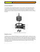
Lynxmotion UAV Electronic Configuration B) Propeller (“Prop”) Balancing Not all propellers are made perfectly, especially those which are made using injection molded plastic. These propellers may not be perfectly balanced and can have more weight on one side than the other. An unbalanced propeller will lead to vibration in the motor, which is transferred to the frame and ultimately to the electronics and sensors. If the sensors are receiving erratic information, the drone will not fly as well as it could.
Lynxmotion UAV Electronic Configuration C) ESC Wire Preparation Each ESC has a buildin BEC (battery eliminator circuit) that provides 5VDC to the red wire on the R/C connector and is used to power the receiver from the main battery. This eliminates the need for one battery for the receiver / controller and another for the motors. Only one ESC needs to provide power to the flight controller / receiver. Remove the red (power) wire from three out of four ESC connectors.
Lynxmotion UAV Electronic Configuration D) Motor Installation In rare cases, it may be important to balance a motor. However, motors purchased through Lynxmotion should not need to be balanced. You can now mount the motors to the frame. If needed, you can disconnect (and then reconnect) the ESC. We suggest running the wires through the arms. It is best to orient the connector / wires along the UAV’s arm when orienting the motor.
Lynxmotion UAV Electronic Configuration STEP 2: Connections A) Power Harness Each ESC needs to be powered directly from the battery. As such, a power distribution board (PDB) or power wiring harness is used to split the battery to four separate connectors. Plug in each of the ESCs to one connector on the harness. We suggest running this harness between the center middle and lower middle plates before you make the connections. Note that the fifth connector connects to the battery.
Lynxmotion UAV Electronic Configuration B) Install Flight Controller Ensure all of the R/C cables from all of the ESCs protrude from the center plate and can easily be accessed. You can now install the flight controller to the frame using the screws provided. The USB connector on the controller (FLIP / MultiWii) faces the FRONT of the copter (this may not be the case for all flight controllers).
Lynxmotion UAV Electronic Configuration MultiWii Flip Pinout Connect the ESCs to the flight controller, ensuring the white / yellow signal (S) pin is at the top.
Lynxmotion UAV Electronic Configuration Yellow / signal pin is connected to the top pin. As indicated in the ESC wire preparation step, only ONE of the ESCs should have the red wire connected. E) Receiver -> Multiwii The R/C hobby receiver you are using should have at least four or five channels.
Lynxmotion UAV Electronic Configuration Receiver to MultiWii. Note that not all connections may line up perfectly as above Once again, the flight controller should be mounted to the frame with the USB port facing the front of the UAV to ensure the orientation of the sensors is correct.
Lynxmotion UAV Electronic Configuration F) Channel Directions WARNING Your propellers should NOT be installed You can now verify all channels to be sure they move correctly. Open the MultiWii Conf. GUI and locate the following window: 1. 2.
Lynxmotion UAV Electronic Configuration G) Install Propellers Example of propeller mounting on a standard quad Notice the direction of each arrow around the pin number above; this indicates the direction that propeller should turn. The leading edge is the one at the top of the propeller, and the trailing edge (usually very thin) is the one at the “rear”.
Lynxmotion UAV Electronic Configuration Common propeller orientation and pinout for FLIP MultiWii Controller Note that the direction of rotation for the Quad X configuration may change from drawing to drawing; the important part is the respective orientation (D3 and D9 should rotate the same way, as should D10 and D11).
Lynxmotion UAV Electronic Configuration In a VTail, the two rear propellers still need to be pushing air DOWNWARDS. Therefore despite the motor being upside down, the propeller should have the top facing up. Notice the top of the propeller is still facing upwards in the Vtail H) Receiver Placement The receiver does not weigh much, but it’s important that it be secured to the frame.
Lynxmotion UAV Electronic Configuration ○ Keep it as far away from electrical devices as possible, especially the power distribution section, batteries and anything that can conduct electricity etc. ○ Never cut, fold, twist or knot the antenna wire ○ Consider using a clear plastic tube in order to keep the antenna straight Step 3: Location You can now plan your first flight. Location and weather conditions are very important and despite your best effort, you can expect to crash a few times.
Lynxmotion UAV Electronic Configuration you create “anchors” which can be made using string and extend from the landing gear to anchor points on the floor. Ensure the length of string is enough to allow the UAV to hover, but is short enough to prevent it from hitting objects in the room. You should also put something relatively soft under the flight area such as a thin carpet.
Lynxmotion UAV Electronic Configuration A transponder allows each aircraft to be picked up by radar and assigned a specific code which describes that aircraft. Almost no small UAVs have a transponder as it adds significant weight, the UAV will be visible to all aircraft (which is not necessarily good) and there is a yearly fee. The FLIP MWC flight controller does NOT have a transponder. Step 4: Pre-Flight Checklist At this point, all connections on the UAV should be made (except for the battery).
Lynxmotion UAV Electronic Configuration Now that you can arm and disarm the motors, arm them once again they should start to rotate. Check (VERY CAREFULLY) that the rotors are all pushing air downwards (but don’t actually take off). If a rotor is pushing air upwards, you will feel it from above, and this needs to be corrected. Practice steps 1 to 9 above until it becomes second nature. Range Test It is really rare that an RC transmitter manufacturer will indicate the range of the remote control.