Lynxmotion UAV Quadrino Nano User Guide Quadrino Nano User Guide V1.0 July 2015 Lynxmotion UAV P.
Lynxmotion UAV Quadrino Nano User Guide Table of Contents 1 Product Description 2 Quick Start 2.1 MultiWii Setup & Load 2.2 Frame Mounting 2.2.1 Double Sided Tape 2.2.2 Through Hole 2.3 Electrical Connections 2.3.1 GPS Antenna 2.3.2 Receiver 2.3.3 Motor Controller (ESC) 2.3.5 Types & PinOut 2.5 WinGUI 2.5.1 Serial Connection 2.5.2 Sensors Calibration 2.5.1 Sensors Orientation 2.5.2 Receiver & End Points 2.5.3 ESC Calibration: 2.5.4 Arming Test 2.5.5 Flight Modes 2.
Lynxmotion UAV Quadrino Nano User Guide 2 - Quick Start We named this section “Quick Start” as it will guide you on all the steps required for the setup of your Quadrino Nano flight controller on a Copter. There are many steps and each one is important so please go over them at least once before performing any steps.. 2.1 - MultiWii Setup & Load Load the Quadrino Nano with your choice of Copter options with the FCT (Firmware Configuration Tool).
Lynxmotion UAV Quadrino Nano User Guide 2.2.2 Through Hole If you have a frame that doesn’t allow you to mount the Quadrino Nano on the center using the double sided tape, you can use our through hole hardware provided with a 30.5mm spacing. Precaution must be taken when handling the bare PCB. Material Needed ● ● ● ● ● ● 4x 256 x ⅞” Hex Screw 4x ⅛” Nylon Spacer 4x #2 Flat Washer 4x 226 Locknut 1x 3/32” Hex Key 1x 5/64” Hex Key 1.
Lynxmotion UAV Quadrino Nano User Guide 2.3 - Electrical Connections A few mandatory connections need to be performed in order to get a fully working Quadrino Nano flight controller. 2.3.1 - GPS Antenna The provided GPS antenna needs to be connected to the front SMA connector. Be sure to properly insert the thread all the way down and don’t apply too much torque. 2.3.
Lynxmotion UAV Quadrino Nano User Guide 2.3.3 - Motor Controller (ESC) Each of the ESCs need to be connected to the Quadrino Nano. One of the ESCs will power the flight controller with its internal voltage regulator (BEC), which is why only one of the ESCs’ connectors has all three wires (GND / +5V / Signal) and the other ones only have the signal wire. Use the 2.3.4 Types & PinOut to know how to connect each of your ESC’s corresponding to your copter type.
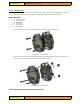
Lynxmotion UAV Quadrino Nano User Guide 2.3.5 - Types & PinOut Here are all the MultiWii supported copter types and their corresponding PinOut connection for an ATmega 2560 based flight controller like the Quadrino Nano. The numbers give you where to connect the corresponding ESC and the rotation is given by the arrow. All Orange arrows show the top motors and Yellow the bottom ones. Note: This is a different PinOut than a ATmega 328P based controller.
Lynxmotion UAV Quadrino Nano User Guide MultiWii Hexacopter Connections MultiWii Octocopter Connections MultiWii Others Connections Lynxmotion UAV P.
Lynxmotion UAV Quadrino Nano User Guide 2.5 - WinGUI WinGUI settings and tests need to be performed in order to get the best out of your Quadrino Nano flight controller. 2.5.1 - Serial Connection A serial connection between the Quadrino Nano and WinGUI need to be initiated. They will share information and allow for setting up all the needed options. Before starting WinGUI, make sure the Quadrino is connected with it’s USB cable unless the COM port will not be available in the dropdown menu.
Lynxmotion UAV Quadrino Nano User Guide 2.5.1 - Sensors Orientation With the “Flight Deck” tab opened, use the various dials to verify the sensor's orientation as well as the installation of the Quadrino Nano on your copter frame. 1. Pitch forward: The Horizon brown portion will get bigger and blue smaller WinGUI Horizon Pitch Forward 2. Turn on it’s Left: The Horizon line will turn to the left. WinGUI Horizon Turn Left 3.
Lynxmotion UAV Quadrino Nano User Guide 2.5.2 - Receiver & End Points You have a live view of what the Quadrino Nano reads from your R/C receiver. Still in the “Flight Deck” tab, look at the Receiver information at the top right. You should be able to make the signals move on each of the connections. Note: The Receiver, if the Quadrino Nano is properly wired, can be powered by the USB cable. WinGUI Receiver LiveView 1.
Lynxmotion UAV Quadrino Nano User Guide 2.5.3 - ESC Calibration: In a multi rotor UAV, each motor is connected to its own electronic speed controller (“ESC”), which is then connected to the flight controller. The ESCs do not “know” the range of values which they will receive from the controller as each controller is different. Calibrating the ESCs provides new min / max throttle values and will also ensure that all motors start simultaneously. 1.
Lynxmotion UAV Quadrino Nano User Guide To set the flight mode, you need to check the box according to the High Mid Low state of your auxiliary switch that you want the Mode to be activated. You need to click “Write Settings” after making changes for them to be loaded into your Quadrino Nano.
Lynxmotion UAV Quadrino Nano User Guide MultiWii Flight Modes Explanation: ● ACRO (Default mode and not in list): Made for Acrobatic flight and is the default setting (uses gyro only)This is the default mode when the HORIZON or ANGLE mode are not activated and is more “acrobatic” flight ● ARM: Arming is a safety feature which is required in order for the motors to start spinning (at below takeoff speed) or stop spinning (after landing).
Lynxmotion UAV Quadrino Nano User Guide 2.6 - Pre-Flight Check Now that you have your copter ready to fly you need to do a proper preflight check. This means starting up the motors at the lowest power level and performing some basic checks. It may be best to do these checks on your floor with the propellers off. (Setup in WinGUI need to be done prior to proceed with those checks) 2.6.1 - Pre-Flight Steps 1. 2. 3.
Lynxmotion UAV Quadrino Nano User Guide 3 - Ports Pinouts Quadrino Nano I2C & UART Pinout Quadrino Nano 20 Pins IO Pinout Lynxmotion UAV P.