Lynxmotion SSC-32U Servo Controller Board Electronics Guide Lynxmotion SSC-32U USB Servo Controller Board Revisions V1.2 July 2017 Feedback / Errata / Support: http://www.robotshop.
Lynxmotion SSC-32U Servo Controller Board Electronics Guide Table of Contents Table of Contents Overview Digital vs Analog vs “Smart” Servos Analog Servos R/C Servo Basics Continuous Rotation Servo Digital R/C Servo Smart Servo Hardware Information Power Options Power Considerations Communication / Control Options USB TTL UART (TX / RX / G Pins) XBee headers SSC-32U / BotBoarduino / PS2 Commands Command Types and Groups. Single Servo Commands Multiple servo command (a.k.a.
Lynxmotion SSC-32U Servo Controller Board Electronics Guide Overview The Lynxmotion SSC-32U is a versatile and easy to use R/C servo controller, the core of which is an Atmel ATmega328p.
Lynxmotion SSC-32U Servo Controller Board Electronics Guide Digital vs Analog vs “Smart” Servos Analog Servos R/C Servo Basics When dealing with a Remotely Controlled (“R/C”) servo, it is important to know the following terminology: ● Case (normally plastic, sometimes aluminum) ● DC motor (normally brushed, sometimes brushless or more exotic) ● Gears (which reduce the motor’s speed and increase the torque) ● Spline (connection from the last internal gear; fits into the servo horn to make it rotate) ● Horn
Lynxmotion SSC-32U Servo Controller Board Electronics Guide R/C Timed Pulse (repeated every 20ms) Hitec Standard Servo Showing Operating Angle vs Signal When an RC servo reaches a specific angle, it will try its best to retain that position, provided it keeps receiving the signal every 20ms. If the torque is higher than what the servo can provide, the current will increase drastically, causing the servo to heat up and eventually fail. Most R/C servos have a duty cycle of around 25%.
Lynxmotion SSC-32U Servo Controller Board Electronics Guide Continuous Rotation Servo A continuous rotation RC servo uses the same pulses / control as a normal analog RC servo but instead converts the pulses to speed and direction, where 1.5ms corresponds to stopped, 0.5ms is full speed counter-clockwise and 2.5ms is full speed clockwise. Intermediate values corresponds to intermediate speeds.
Lynxmotion SSC-32U Servo Controller Board Electronics Guide Hardware Information Dimensions SSC-32U Board Dimensions (inches) The SSC-32U is 3.00" x 2.30" with 0.125" holes set in 0.15" from each edge. It was designed to the same dimensions as the Lynxmotion BotBoarduino, the Lynxmotion SSC-32 (its predecessor), the Lynxmotion Bot Board and Bot Board 2 so they could be stacked.
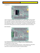
Lynxmotion SSC-32U Servo Controller Board Electronics Guide S1 Pins The SSC-32U servo controller can control up to 32 servos, which are laid out as two separate sections of 16 servos, each grouped together in sets of four. Pins 0 to 15 corresponds to VS1. The outermost pin (farthest from the center of the board) is the ground pin (normally the black wire in a three pin cable). The center pin corresponds to the voltage (normally the red wire) and is marked with VS1.
Lynxmotion SSC-32U Servo Controller Board Electronics Guide Analog IO Pins There are 8 I/O pins included on the board labeled ‘A’ to ‘H’. The row of pins on the left marked with ‘G’ correspond to ground (normally the black wire on a three pin cable). The center row of pins, marked with ‘5’ provides 5V output (normally the red wire). The last row of pins (no label) is for the signal. Two of these pins can also be used for I2C, with pin A corresponding to SCL and pin B corresponding to SDA.
Lynxmotion SSC-32U Servo Controller Board Electronics Guide VS = VL These two pins allow you to tie the VS1 terminal to VL (i.e. VL = VS). This would have the same effect as running a wire from from the VS1+ screw terminal to the VL+ screw terminal. Please refer to the power section of this guide for important information. A jumper for these pins is not included. VS1 = VS2 These 2x2 pins allow you to set VS1 = VS2.
Lynxmotion SSC-32U Servo Controller Board Electronics Guide XBee The XBee headers allow you to connect an XBee wireless module other XBee compatible devices. Take note of the image on the board for how to orient the module. Please refer to the communication / control section in this guide for more information. USB Commands can be sent to the SSC-32U’s microprocessor from the computer via the onboard USB port.
Lynxmotion SSC-32U Servo Controller Board Electronics Guide Tx Rx The two LEDs next to the USB port provide the user with visual feedback of when data is received (Rx) and if data is transmitted (Tx). These are only associated with communication via the USB port and not the XBee header or serial pins. Serial The three pins behind the FTDI chip are Tx, Rx and GND. Commands sent from the SSC-32U are done using the Tx pin while commands to be received by the SSC-32U are done via the Rx pin.
Lynxmotion SSC-32U Servo Controller Board Electronics Guide A/B LEDs There are two distinct LEDs on the board labeled A and B When not setting the Baud rate, the LEDs indicate the following: ● Both ON at power-up before a byte is received. ● Green flashes when a valid byte is received. ● Red flashes when an invalid byte is received (framing error). For more information, please refer to the Baud section in this guide. 5G Pins These pins are normally not needed, and pins are not provided.
Lynxmotion SSC-32U Servo Controller Board Electronics Guide RSSI RSSI stands for “Received Signal Strength Indication” and the LED is connected to pin 6 of the Xbee socket. Different blink intervals are used to indicate different status based on the module chosen. PWR The PWR LED is connected to V_logic which is the equivalent of MAX(VL, VS1) minus roughly 0.7V. It's the voltage that's then regulated to 5V for powering the logic circuits.
Lynxmotion SSC-32U Servo Controller Board Electronics Guide Power Options USB When the board is connected to a computer via USB, the onboard USB to serial chip will be powered and your computer will be able to detect it and install the drivers. The USB does not however power the the main ATmega chip, so it must be powered separately through VS1 or VL. VL Screw Terminal The VL screw terminals allow for unregulated inputs to the logic voltage (the voltage used by the main processor / chip).
Lynxmotion SSC-32U Servo Controller Board Electronics Guide VS1 = VS2 Jumpers The second half of servo pins numbered 16-31 can be powered using the same power source as VS1 by leaving the two VS1=VS2 jumpers in place. There are two jumpers (rather than just one) because of the current involved. Should you want to power the line of servos connected to VS2 separately from VS1, you can remove these two jumpers. If you have the two VS1 = VS2 terminals in place, you can power EITHER VS1 or VS2, but not both.
Lynxmotion SSC-32U Servo Controller Board Electronics Guide Power Considerations The SSC-32U board does not read the battery’s voltage, and will continue to function even if a battery is being deeply discharged. It is up to the user to ensure that the pack’s voltage is maintained above a certain voltage or there will be a risk of irreparably damaging the battery.
Lynxmotion SSC-32U Servo Controller Board Electronics Guide Battery Chemistry & Current Alkaline Alkaline batteries are most commonly found as single cell 9V, AAA, AA, C and D. These batteries are not rechargeable and are usually 1.5V. You can use four 1.5V cells to make a 6V battery pack. The battery’s capacity is rarely indicated on the cells, so it is difficult to gauge just how long they will last. If the battery is inexpensive, you can assume it will not last for long.
Lynxmotion SSC-32U Servo Controller Board Electronics Guide Communication / Control Options There are three ways to communicate with the SSC-32U board: USB, TTL UART, and XBee socket. We recommend only using one, but USB will have priority if multiple are used.
Lynxmotion SSC-32U Servo Controller Board Electronics Guide USB You can connect the board to a standard desktop or laptop computer using a normal USB cable (miniB to A). Once the USB cable is connected, your computer should automatically detect it and install the appropriate drivers to let the board appear as a COM port and allow programs on your computer to communicate with the board.
Lynxmotion SSC-32U Servo Controller Board Electronics Guide TTL UART (TX / RX / G Pins) Commands can be sent to the SSC-32 using the serial pins on the board. There are two ways the BotBoarduino can be connected to the SSC-32 1. Direct serial connection ● TX from the BotBoarduino to RX on the SSC-32U ● RX from the BotBoarduino to TX on the SSC-32U ● GND on the BotBoarduino to GND on the SSC-32U 2. Software Serial (allowing you to connect other devices to the BotBoarduino’s serial pins).
Lynxmotion SSC-32U Servo Controller Board Electronics Guide XBee headers The XBee socket on the SSC-32U can be used with a variety of wireless devices including: ● Bluetooth modules with XBee footprint ● XBee modules ● RF modules with XBee footprint SSC-32U with Bluetooth Bee Installed Note the orientation of the module matches that of the silkscreen on the board.
Lynxmotion SSC-32U Servo Controller Board Electronics Guide SSC-32U / BotBoarduino / PS2 The SSC-32U can be used with the BotBoarduino (and normal Arduinos), which itself is optionally connected to a PS2 controller. The Lynxmotion PS2 receiver and levelshifter is shown.
Lynxmotion SSC-32U Servo Controller Board Electronics Guide Commands Command Types and Groups. Single Servo Commands In order for the SSC-32 to position a servo, it must receive a serial command in the following format. Note that the less than and greater than signs are not needed. Values in italic are optional.
Lynxmotion SSC-32U Servo Controller Board Electronics Guide Example 2 will move servo 3 to position 1600. It will take 1 second to complete the move regardless of how far the servo has to travel to reach the destination. Multiple servo command (a.k.a. “Command Group”) The SSC-32U allows for multiple commands to be received in the same string. For servo position, this may look like: # P S ...
Lynxmotion SSC-32U Servo Controller Board Electronics Guide Any move that involves more than one servo and uses either the S or T modifier is considered a Group Move, and all servos will start and stop moving at the same time. If you require moving several servos at different speeds, you must issue the commands separately. Software Position Offset. Servo Position Offset # PO ... # PO ...
Lynxmotion SSC-32U Servo Controller Board Electronics Guide 12 Servo Hexapod Sequencer The SSC-32U includes a built-in function to easily control a 12 degree of freedom (six legs, two degrees of freedom per leg) hexapod walking robot. The function still requires serial commands to be sent from an external source (microcontroller, computer or wireless module).
Lynxmotion SSC-32U Servo Controller Board Electronics Guide Visual Pin Assignment for Hexapod Sequencer The walking sequence consists of 8 states, numbered 0-7. The gait uses an alternating tripod gait (three legs up, three legs down) to walking, with six possible locations of each foot. The tripods are labeled Tripod A and Tripod B.
Lynxmotion SSC-32U Servo Controller Board Electronics Guide Position & Motion of Foot During Motion Walking Gait Configuration LH , LM , LL Set the value for the vertical servos on the left side of the hexapod. LH sets the high value, i.e. the pulse width to raise the leg to its maximum height; LM sets the mid value; and LL sets the low value. The valid range for the arguments is 500 to 2500uS.
Lynxmotion SSC-32U Servo Controller Board Electronics Guide VS Sets the speed for movement of vertical servos. All vertical servo moves use this speed. Valid range is 0 to 65535uS/Sec. LF , LR Set the value for the horizontal servos on the left side of the robot. LF sets the front value, i.e. the pulse width to move the leg to the maximum forward position; LR sets the rear value. The valid range for the arguments is 500 to 2500uS.
Lynxmotion SSC-32U Servo Controller Board Electronics Guide XSTOP Stop the hex sequencer. Return all servos to normal operation. 1. When a horizontal servo is moving, its speed will be adjusted based on the Front/Rear pulse widths, the XL/XR percentage, and the XS percentage. Regardless of the travel distance from front to rear (adjusted by XL/XR), the total move time will be the HT divided by the XS percentage. 2.
Lynxmotion SSC-32U Servo Controller Board Electronics Guide Advanced Functions Cancel Output # P …. ● : Cancel the current action, ASCII 27 Should you wish to cancel a command, add an to the end of the line: Discrete Output The IO pins on the SSC-32 can be used to provide HIGH (5V) or LOW (0V) signals. Note that you should NOT use this function with standard RC servos. # ...
Lynxmotion SSC-32U Servo Controller Board Electronics Guide This example will output the value 123 (decimal) to bank 3. 123 (dec) = 01111011 (bin), and bank 3 is associated with pins 24-31. So this command will output a "0" to pins 26 and 31, and will output a "1" to all other pins. Query Movement Status Q This will return a "." if the previous move is complete, or a "+" if it is still in progress. There will be a delay of 50uS to 5mS before the response is sent.
Lynxmotion SSC-32U Servo Controller Board Electronics Guide Analog Inputs VA VB VC VD VE VF VG VH Pins labelled A to H are analog input / output pins which can be used to read sensors, to drive low power LEDs etc. Example: "VA VB VC VD " VA, VB, VC, and VD read the value on the input as analog. It returns a single byte with the 8-bit (binary) value for the voltage on the pin. When the ABCD inputs are used as analog inputs the internal pullup is disabled.
Lynxmotion SSC-32U Servo Controller Board Electronics Guide stored as 960. For example, to set to 2400 Baud, issue the command R4=240. In this case, pressing the button will not light the LEDs, indicating the Baud rate is non-standard. (It will blink the LEDs briefly when pressed, just so you will know something happened.) You can read back the current Baud rate by just entering the command "R4" followed by a carriage return. "R4" will result in "240" if the Baud rate is 2400.
Lynxmotion SSC-32U Servo Controller Board Electronics Guide Firmware To update the firmware, use the free SSC-32 Servo Sequencer Utility (RB_Dsp-07) SSC-32 Registers Register General Info Number Name Minimum Maximum Default Description 0 Enable 0 65535 0 A bit field (16 bits) that enables various features of the SSC-32. 1 Transmit Delay 0 65535 600 The delay, in microseconds, before transmitting the first byte of a response from the SSC-32.
Lynxmotion SSC-32U Servo Controller Board Electronics Guide Enable Register (R0) Bit Definitions Bit Name Definition 15 (msb) Global Disable If '1', disables all of the featured controlled by the Enable register. If '0', the individual bit values will be used to enable or disable the features. 14-4 (Reserved) -- 3 Initial Pulse Width Enable If '1', enables the Initial Pulse Width register values at startup. If '0', the default value of 0 will be used.
Lynxmotion SSC-32U Servo Controller Board Electronics Guide If an RDFLT or R= command is executing, do not power down the SSC-32 until the command has completed. To determine whether the command has completed, read a register value. Each time a register is written, the EEPROM location(s) used to store the value experience a small amount of wearout. The typical maximum number of writes is 100,000.
Lynxmotion SSC-32U Servo Controller Board Electronics Guide Startup Strings Command Argument Description / Examples Delete characters: SSDEL 0-255 Deletes characters from the end of the startup string. If is greater than the length of the startup string, then SSDEL deletes the entire string.
Lynxmotion SSC-32U Servo Controller Board Electronics Guide Startup String Examples Command Result SSDEL 255 SS "" SSCAT #0P2000T5000; SS "#0P2000T5000;" SSCAT XXXX SSC "#0P2000T5000;XXXX" SSDEL 4 SS "#0P2000T5000;" SSDEL 6 SS "#0P2000" SSCAT #1P1000T4000;PL0SQ5; SS "#0P2000#1P1000T4000;PL0S Q5;" Additional Examples Command Result RDFLT Set all registers to default values SSDEL 255 Erase the startup string
Lynxmotion SSC-32U Servo Controller Board Electronics Guide 41