
Instruction Manual


IMPORTANT: Whenever one of the front panel high impedance
i
nputs is used, the associated back panel XLR is disabled.
The Audio Buddy also has built in phantom power which can be
switched on or off for both channels. When the rear panel phantom
p
ower switch is in, phantom power to both channels is turned on and
the front Phan(tom) power LED will light.
IMPORTANT: Since the phantom power switch turns phantom
power on or off for both channels, there is no way to turn phantom
p
ower on for one channel and off for the other channel. If you are
using the high impedance inputs the phantom power switch has no
effect.
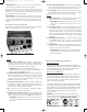
Front and Real Panels
When reading the following description of front and rear panel harware
f
eatures, it may be helpful to refer to the adjacent diagram.
Front
1. High Impedance Input 1: High impedance (100K) input for
Preamp 1. This input is optimized for guitars or high impedance
microphones where you don’t want to load down the source.
When this input is being used XLR input 1 is disabled.
I
M
P
ORTANT:
Because the high impedance input jack is
switched, the XLR input cannot be used whenever something is
plugged into the high impedance input.
2. Sig(nal) and Clip LED Preamp 1: Whenever a signal is applied to
either the high impedance ”In” or the XLR “In” of Preamp 1, these
LE
Ds will show signal present and clipping levels. If a signal is
applied in this manner and the clipping LED lights too much adjust
the Preamp 1 gain control accordingly.
3. Gain Control for Preamp 1: Adjusts the Output 1 volume level
for Preamp 1. If a signal is present at either the high impedance in
or the X
LR in of Preamp 1 and the Clipping LED stays lit, turn
down this gain control and adjust accordingly.
4,
5, 6.
S
ame as 1, 2 and 3 for Preamp 2. Remember, Preamp 1
and Preamp 2 are completely independent.
7
.
Phantom Power Indicator LED
: W
hen the phantom power
switch on the back of the unit is in, this LED will light indicating that
phantom power has been turned on for
both XLR in 1 and XLR 2.
I
M
P
ORT
ANT
: Phantom power is turned on for both preamps,
i.e. there is no independent phantom power control for each of
the c
hannels.
Warranty and Registration
Warranty Terms
M-Audio warrants products to be free from defects in materials and
workmanship, under normal use and provided that the product is owned
by the original, registered user. Visit www.m-audio.com/warranty for
terms and limit
ations applying to your specific product.
W
arranty Registration
Immediately registering your new M-Audio product entitles you to
full warranty coverage and helps M-Audio develop and manufacture
the finest quality products available. Register online at www
.m-
audio.com/register to receive FREE product updates and for the
chance to win M-Audio giveaways.
© 2
008 A
vid T
ec
hnology, Inc. All rights reserved. Product features,
specifications, system requirements and availability are subject to
c
hange without notice. Avid, M-Audio and Audio Buddy are either
trademarks or registered trademarks of A
vid Tec
hnology
, Inc. All
other trademarks contained herein are the property of their
respective owners.
WARNING: This product contains chemicals, including lead,
known to the St
ate of California to cause cancer
, and birth defects
or other reproductive harm.
Wash hands after handling.
8. Main Power Indicator LED: When power is properly applied
t
o the Audio Buddy and when the front power switch is in, the
main power LED will light indicating that the unit is turned on.
9
. Power Switch:
W
hen power is properly applied to the Audio
Buddy and this switch is pressed in, the Audio Buddy is turned
on. When this is done the Main Power LED will light.
Rear
10. 9-VAC Power Jack. The rear panel power jack of the Audio
Buddy accepts a 9-Volt AC, 500 milliamp power adapter.
IMPORTANT: Audio Buddy will not function unless it receives
power at this jack and the front panel power switch is
p
ushed in.
11, 12. Outputs 2 and 1: These are the main outputs for the dual
A
udio Buddy preamps. They provide unbalanced outputs if a
tip-sleeve 1/4” plug is used. Or, they provide balanced outputs
if a tip-ring-sleeve (stereo) 1/4” plug is used. The level of these
o
utputs are independently controlled by the front panel gain
controls. Remember, Preamp 1 and Preamp 2 are completely
independent.
13. Phantom Power Switch: When in, phantom power is turned
on for
both XLR In 1 and In 2. When in, the front panel
phantom power indicator LED will light showing that phantom
power is on.
14, 15. XLR-In1&2: (#15 is 1; #14 is 2) Balanced XLR inputs for
preamps 1 and 2. When the rear phantom power switch is in,
phantom power is turned on to both jacks.
IMPORTANT: If anything is plugged into either of the front-
panel high-impedance input jacks, the corresponding XLR
input will be disabled.
AudioBuddyUG_Aug07.qxd 5/19/08 11:17 AM Page 2