Delta 66 ™ MANUAL Version D66 122700 Table of Contents Introduction . . . . . . . . . . . . . . . . . . . . . . . . . . . . . . . . . . . . . . . . . . . . . . . . . . 2 What’s in the Box? . . . . . . . . . . . . . . . . . . . . . . . . . . . . . . . . . . . . . . . . . . . . . 2 About the Delta 66 Digital Recording Interface . . . . . . . . . . . . . . . . . . . . . . . 2 Product Features & Specifications . . . . . . . . . . . . . . . . . . . . . . . . . . . . . . . . . 3 Minimum System Requirements . .
Introduction Congratulations on your purchase of the Delta 66 Digital Recording Interface designed and built by M Audio. Even if you are experienced in digital recording, please take the time to read this manual. It will give you valuable information on installing your new card and the supporting software, plus help you to fully understand the function and usability of the Delta 66.
Product Features & Specifications • • • • • • • • • 6x6 24-bit/96khz full-duplex recording interface. PCI host card with external break-out box. 4x4 analog I/O accepts balanced or unbalanced connections on 1/4” TRS jacks. Analog I/O configurable for +4dBu, Consumer, and –10dBV signal levels. Analog dynamic range exceeding 103dB. All data paths support up to 24bit/96kHz performance, no upgrades necessary.
5 6 3 2 1 Break-Out Box Front Panel: 1. 2. Analog OUTS 1-4: These jacks output analog audio to a variety of external sources. Each jack is 1/4” TRS (Tip-Ring-Sleeve) and is compatible with 1/4” TRS (balanced) or TS (Tip-Sleeve unbalanced) connections. Analog INS 1-4: These jacks input analog audio from a variety of external sources. Each jack is 1/4” TRS (Tip-Ring-Sleeve) and is compatible with 1/4” TRS (balanced) or TS (Tip-sleeve unbalanced) connections. Break-Out Box Back Panel: 3.
. 6. Coaxial S/PDIF Output: This RCA connector sends an S/PDIF stereo signal to your coaxial S/PDIF digital target device such as a DAT, MiniDisc player or external D/A converter. Host Cable connector: This 15-pin D-sub connector attaches to the supplied host cable to allow communication between the PCI host card and the breakout box. Quick Guide to Getting Started Here is a list of the steps required to get your Delta 66 up and running: 1. 2. 3. 4. 5.
5. 6. 7. 8. you want to be doubly sure you aren’t carrying a static charge that could damage the card. Remove the metal bracket that covers the access hole on the back of the computer. This bracket is usually fastened to the computer with a single screw. Position the Delta 66 PCI host card over the target PCI slot and fit the card loosely over it with the card in the upright position. Press the card gently but firmly downward into the slot until the card is completely and squarely seated in the slot.
2. 3. 4. 5. 6. The ‘Add New Hardware Wizard’ will now ask how to locate the driver. “Search for the best driver for your device” is already selected. Click ‘Next>’. Windows will give you a selection of locations to search. Make sure that only “Choose a Path” is checked, or click on the check box to do so. Insert the Drivers CD into your CD ROM drive. Type in the drive letter of your CD drive (we will assume here that it is D:\) and the path to the Delta drivers, which will be D:\Delta Products\Delta98.
4. work in Win95). Click ‘Next>’. Windows will start to copy files, with a progress indicator on the screen. Once this process completes itself, your Delta 66 will be ready for action. After completion of the driver installation, Windows may require you to restart Windows. If it does request a restart, remove the Drivers CD from the CD drive and respond by clicking “Yes”. The system will restart and your Delta 66 is ready for play. Windows NT Installation 1. 2. 3. 4. 5. 6.
5. 6. panel by highlighting it and pressing Command (Apple key)+M. Then, drag the alias to the desktop. With the Delta 66 PCI card installed, restarting the computer will load the Delta 66 extension. You will be able to visually see the Delta extension icon pass by as your system loads extension. Go to the Apple menu |Control Panel | Sound. You should see the “built-in” sound icon, plus the Delta icon if your Delta 66 is properly installed.
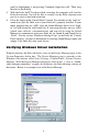
This example shows the M Audio Delta 66 and Midiman WINMAN 4x4/S (another product shown here only as an example) entries in the Windows Device Manager device list. The Delta 66 is properly installed with no conflicts, as is the WINMAN 4x4/S. If you do not see your M Audio Delta 66 in your Device Manager in this fashion, please jump ahead to the “Troubleshooting” section of this manual.
mixers. Selecting the ‘–10’ setting sets up the channel(s) for -10dBV nominal signal levels, commonly used with consumer equipment such as CD, MiniDisc, cassette tape and DAT players. The ‘Consumer’ setting is preferred for semi-pro audio equipment and some consumer equipment that is too ‘hot’ for the ‘-10’ setting. The ‘Consumer’ setting offers approximately 6dB more headroom than does the ‘-10’ setting.
Synchronization For proper operation, the entire Delta 66 system is always synchronized to a single master clock. The master clock is chosen via the Delta Control Panel software and this clock may be derived from either the Delta 66’s internal crystal oscillators or S/PDIF In. Most of the time the master clock is taken from the internal crystal oscillators. However, the S/PDIF option is used in situations where the Delta 66 must be synchronized to external digital audio or sample rates.
software application(s), the names of the Delta 66 audio input devices are: PCM In 1/2 Delta-66 PCM In 3/4 Delta-66 S/PDIF In Delta-66 Mon.Mixer Delta-66 The PCM In devices allow recording a stereo stream directly from the specified analog input pairs. The S/PDIF In device allows you to record a stereo stream directly from the S/PDIF input. The Mon.Mixer device allows stereo recording from the digital “monitor” mixer built-into the Delta 66.
MACINTOSH SOUND MANAGER INPUTS AND OUTPUTS: The Apple Sound Manager limits the user to one stereo pair for input and one stereo pair for output. Within your music software, the device selection when using the Sound Manager drivers for input and output will be “Sound Manager” both for input source and for output port. To select the Sound Manager driver, open the Apple Menu and go to Control Panel | Sound. For both “Sound In”and “Sound Out,” click and highlight the Delta icon, then exit.
Windows. To set this up, go to Control Panel | Multimedia. In the Audio Properties page, set the Playback and Recording devices to the Delta 66 input and output devices of your choice. Delta 66 Control Panel Software ON THE PC: Once the Delta 66 is properly installed, an "M Audio Delta H/W" icon will be displayed in your Windows Control Panel. By double-clicking on that icon, you will launch the Delta Control Panel software.
The Monitor Mixer Page is essentially a collection of volume level faders, audio level (or ‘peak’) meters, and solo/mute controls. For each mixer output and input channel there is one of each: a volume fader, a peak meter, a solo control, and a mute control. LEVEL FADERS: Each volume fader may be controlled by dragging its fader ‘handle’ vertically with the mouse, or by clicking on the ‘handle’ to make it active and then adjusting it with the up/down cursor keys of your computer keyboard.
indicates overload and audio clipping may occur. Therefore be careful to adjust the incoming audio levels so that they do not peak in the red section too long (you might use the monitoring capability of the Delta 66 to let your ears be the judge). On all output level meters, 0dB indicates full-scale output. Unlike the inputs, hardware clipping is impossible on the outputs because of the 36-bit resolution built into the mixer hardware.
adjustment (in 1% increments), you may click on the pan control to make it active, and then use the left/right or up/down cursor keys on your computer keyboard. Either way, while the pan setting is being adjusted, its value will appear numerically in the Master Volume’s status box (below the Master Volume Stereo Gang control) as a percentage from left pan to right pan: -100% represents far left, +100% represents far right, and 0% represents the center.
3. 4. 5. The third option, “S/PDIF In,” connects ports OUT1 and OUT2 directly to the hardware S/PDIF input on the Delta 66 PCI host card. The left channel of the S/PDIF In is routed to OUT1 and the right channel of the S/PDIF In is routed to OUT2. The fourth option, “S/PDIF In (L/R Rev.),” functions identically to the third option, except that the left and right channels are swapped.
2. 3. 4. 5. The second option, “Monitor Mixer,” connects the S/PDIF Out port to the outputs of the Delta 66 monitor mixer. For more information on the capabilities of the monitor mixer, please see the section “Monitor Mixer Page.” The third option, “S/PDIF In,” connects the S/PDIF Out port directly to the hardware S/PDIF input on the Delta 66 PCI host card.
Once a master clock source has been selected, its synchronization status is continually monitored and displayed below the master clock radio buttons. If internal crystal is selected, the status display will always say “Locked.” On the other hand, if S/PDIF In is selected as the master clock source, the control panel will display “Locked” only when a valid S/PDIF signal is detected.
channels will begin playback and/or recording at the same time. Otherwise select “Independent” to allow the audio channels to play independently — this setting may be desirable if more than one application needs to access the Delta 6 6 simultaneously. DMA BUFFER SIZES: This section specifies the amount of system memory dedicated to digital audio buffering. Setting a buffer size that is too small may result in clicks or pops in the audio stream as some data may be lost.
VARIABLE SIGNAL LEVELS: The software switches in this section allow the user to match individual input levels and global (as in ‘all’ or ‘across the board’) output levels to the operating signal levels of the external audio equipment. Three level selections are available: +4dBu, ‘Consumer,’ and –10dBV. The ‘+4dBu’ setting is the least ‘sensitive’of the three settings, and ‘–10dBV’the most sensitive.
or no signal is present, the group box displays “Invalid or Not Present.” Below this message are two ‘grayed-out’ buttons: “Coax(RCA)” and “Optical.” These are functions of the Delta DiO 2496, another product in the M Audio Delta line, one with both optical and coaxial S/PDIF inputs. These controls do not apply to the Delta 66. DIGITAL OUTPUT FORMAT: Within the “Digital Output Format” group, you choose the digital audio format of the S/PDIF output.
indicate or not indicate if pre-emphasis has been applied to the outgoing digital audio signal. The default is “None” and rarely will any user want to set the value to “CCITT” or “50/15uSec” unless the transmitted audio has been encoded with one of those types of pre-emphasis. About Page The “About” page, while displaying the handsome M Audio logo and applicable copyright information, also reports the driver version and control panel software version.
In the upper righthand corner of the control panel is a “H/W Installed” drop-down list. At the time of this writing, the Delta Mac ASIO drivers will support only a single Delta device, and of course the Sound Manager will support only one stereo pair regardless of how many audio cards are installed in your system. The H/W Installed list will display “Delta 66 as the active device in the control panel.
1. 2. 3. 4. Plug the guitar into the channel-1 Line input of the pre-amp. Plug the microphone into the channel-2 Mic input. Plug the outputs 1 & 2 of the pre-amp into the Delta 66’s analog inputs 1 & 2. Both are balanced outputs and inputs (respectively), so use a high quality TRS cable. Most balanced lines run at +4dB line level, so let’s set our +4/Consumer/-10 switches to +4dB on inputs 1 & 2.
music software into which you will be recording. We’ll start with the Delta Control Panel’s “Hardware Settings” page, then the “Patchbay/Router” page, and finally the “Monitor Mixer” page. We’re not using S/PDIF in this example so we’ll ignore the S/PDIF page. 5. 6. 7. 8. Click on the Delta Control Panel on your Windows taskbar to maximize it. Click on the ‘Hardware Settings’tab. Select ‘Internal Xtal’ as the master clock source.
Select the “Monitor Mixer” tab of the Delta Control Panel. The default Master Volume fader settings are 0dB and un-muted, and all other faders are set to full attenuation (-144dB) and muted. We will need to adjust these to our preference. The screen capture below shows the settings that we wish to achieve.
9. In the Mixer Input column labeled “WavOut 1/2,” click on each fader handle and drag it up to the 0dB setting. Also, deactivate (uncheck) each WavOut 1/2 mute box to unmute the channels. This will allow us, once we’ve recorded into a music software program, to hear those software outputs upon playback. 10. Using the scroll bar at the bottom of the control panel, scroll to the right until you see the column labeled “H/W In 1/2.
16. Press record on your software’s transport bar. Record a take of your guitar and vocals. Understand that while recording, you are monitoring the Delta inputs by way of the Monitor Mixer settings for H/W In 1/2, and according to the selection of ‘Monitor Mixer’ within the Patchbay/Router page. At the same time, your software is recording from H/W In 1/2 but at the levels that were set up with the pre-amp. 17. When you are done playing, stop the recording software and rewind the take.
you will be recording the same instruments that you did on the first two tracks, you probably won’t need to adjust input or monitoring levels. 20. Press record on your software’s transport bar. Record a take of your new guitar and vocal tracks. Because you have set up the first two tracks to play back through the monitor mixer, you should hear those original tracks along with the ones that you are now recording. 21. When you are done playing, stop the recording software and rewind the take.
the signal to the Delta 66, and a mixer connected to a sound system to handle the multiple outputs. Let’s say that we’re recording a guitar/vocal duo. We’ve got a mic on each voice, with the guitars going ‘direct’into the pre-amps. NOTE: Because improper connections can potentially make very loud noises, it’s a good idea to have monitor levels down while hooking up audio equipment — you may choose to turn your computer off before making the connections.
1. 2. 3. Plug the microphones into the mic inputs 1 & 2 of the pre-amps. Plug the guitars into the high impedance inputs 3 & 4 of the pre-amps. Plug the outputs of the pre-amps 1-4 into the hardware inputs 1-4 of the Delta 66. Usually pre-amp outputs are balanced, so if they are, use TRS cables and set the Delta +4/Consumer/-10 input switches to the +4dB setting in the Hardware Settings page of the Delta Control Panel.
7. Open your music software program. Set up four tracks for recording: Track one Track two Track three Track four 8. Left PCM In 1/2 Delta-66 Right PCM In 1/2 Delta-66 Left PCM In 3/4 Delta-66 Right PCM In 3/4 Delta-66 Now we want to set up the output ports for the four tracks. Track one Track two Track three Track four 9. — — — — — — — — WavOut 1/2 Delta-66, panned hard left. WavOut 1/2 Delta-66, panned hard right. WavOut 3/4 Delta-66, panned hard left. WavOut 3/4 Delta-66, panned hard right.
Using the Delta 66 and the Delta Control Panel software in this manner may be your choice when using a mixing console to control the monitor and playback levels. If this were a real recording situation and you wished to add other instruments as overdubs, you might want to combine recorded tracks to one stereo pair of outputs (WavOut 1/2 Delta-66, for example). This would ‘free up’ several channels for monitoring the overdubs.
Transferring from DAT to Delta 66 1. 2. 3. 4. 5. Connect the DAT’s coaxial S/PDIF output to the S/PDIF In of the Delta 66 PCI host card, using a good quality cable. Connect the Delta 66 analog outputs 1 & 2 to some type of amplified sound system. The sound system should be equipped with speakers or headphones. Set the software +4/Consumer/-10 switch on the Delta Outputs to be compatible with that sound system’s inputs.
6. 7. Within your recording software, select “S/PDIF In Delta-66,” as the audio input device. The Delta input appears as a stereo pair. Start your software recording and then start your DAT material playing. You should be able to hear the DAT material through your sound system. Transferring from Delta 66 to DAT, monitoring with DAT 1. 2. 3. Connect the Delta 66’s S/PDIF Out to the DAT’s coaxial S/PDIF Input using a good quality cable. Connect the DAT analog outputs to some type of amplified sound system.
4. 5. 6. 7. under Master Clock, selecting “Internal Xtal.” Also, under the Codec Sample Rate section you may uncheck “Rate Locked” if it is previously checked. This allows for more flexible sample rate playback. In order to verify proper S/PDIF Output routing, open the Patchbay/Router page of the control panel software. In the “H/W Out S/PDIF” column, select the radio button named “WavOut S/PDIF.
NOTE: When resolving conflicts between PnP and non-PnP devices, it is recommended to re-adjust the resource settings of the non-PnP device first. Typically, Windows is only aware of the resource settings of the installed PnP devices and has no information available to it for adjusting the PnP devices’ re s o u rces around those of the non-PnP devic es.
Sometimes it is possible that a resource problem is not showing up in the conflicting resource list or as a yellow exclamation point in the Device Manager. If you have any doubt about the configuration of your device (or just want to doublecheck), you can view all of the devices and their assigned resources by highlighting “Computer” at the top of the Device Manager list and clicking the Properties button.
device (non-PnP ISA card), and needs to be told to look for a PCI/ISA PnP device (some systems default to this, especially with IRQs 3 and 4). Consult your computer or motherboard manual for advice on how to do this. Finally, with some systems you will reach the dead-end realization that you have no available IRQ’s — every one of them is assigned to some device in the system. This most typically occurs with pre-packaged computers made by the big-name O.E.M. computer companies.
Problem: Repetitious Sound. Possible Cause: An IRQ resource conflict. Often this will result in a small segment of sound (0.5 to 1 second) repeating itself over and over, sometimes completely locking up the computer. See the general troubleshooting suggestions at the beginning of this section. Problem: I’m getting some pops and clicks in my audio recording. Possible Cause 1: Input levels are too “hot,” causing clipping or input distortion.
Appendix A - Technical Specs Analog Audio Peak Analog Input Signal: Peak Analog Output Signal: Dynamic Range: Outputs: Inputs: THD (at 0dBFS): Outputs: Inputs: Frequency Response: Input Impedance: Input Connectors: Output Connectors: Digital Audio Digital Input Format: Digital Input Sample Rate: Digital Output Format: Digital Output Sample Rate: +14dBu (+4dBu setting), +6dBV (Consumer setting), 0dBV (-10dBV setting). +14dBu (+4dBu setting), +6dBV (Consumer setting).
Appendix B -If You Use An External Mixer... Our main objective is to get the signal we want to record to the Delta 66, and to monitor the outputs from the Delta 66. The Delta 66 has a mixer contained in its PCI chip that allows you to mix hardware inputs and software outputs and send it to an analog stereo output pair and/or the S/PDIF out. The Delta 66 also allows you to record that mix into your music software as a hardware input.
Some line mixers have a number of effect or auxiliary sends for each channel. These sends will have their own individual level control and will receive the signal either pre fader or post fader, i.e. either independent or dependent on that channel’s fader level. It is possible to use these “aux sends” to send a signal to the recording device. A pre fader send is certainly preferable, since this will allow for a recording level that is separate from the monitoring level.
Limited Lifetime Warranty MIDIMAN warrants that this product is free of defects in materials and workmanship under normal use so long as the product is: owned by the original purchaser; the original purchaser has proof of purchase from an authorized MIDIMAN dealer; and the purchaser has registered his/her ownership of the product by sending in the completed warranty card. This warranty explicitly excludes power supplies and included cables which may become defective as a result of normal wear and tear.