Venom User Guide ™
Legal Notices This guide is copyrighted ©2010 by Avid Technology, Inc., with all rights reserved. Under copyright laws, this guide may not be duplicated in whole or in part without the written consent of Avid Technology, Inc. Avid, Pro Tools, Pro Tools M-Powered and M-Audio are either trademarks or registered trademarks of Avid Technology, Inc. All other trademarks contained herein are the property of their respective owners.
Contents Chapter 1. Introduction . . . . . . . . . . . . . . . . . . . . . . . . . . . . . . . . . . . . . . . . . . . . . . . . . . . . . . . . . . . . . . . . . . . . . . . . . . . 1 Venom Features . . . . . . . . . . . . . . . . . . . . . . . . . . . . . . . . . . . . . . . . . . . . . . . . . . . . . . . . . . . . . . . . . . . . . . . . . . . . . . 1 Minimum Requirements . . . . . . . . . . . . . . . . . . . . . . . . . . . . . . . . . . . . . . . . . . . . . . . . . . . . . . . . . . . . . . . . . . .
Appendix B. System Exclusive Implementation . . . . . . . . . . . . . . . . . . . . . . . . . . . . . . . . . . . . . . . . . . . . . . . . . . . 86 SysEx Format . . . . . . . . . . . . . . . . . . . . . . . . . . . . . . . . . . . . . . . . . . . . . . . . . . . . . . . . . . . . . . . . . . . . . . . . . . . . . . . 86 Handshaking . . . . . . . . . . . . . . . . . . . . . . . . . . . . . . . . . . . . . . . . . . . . . . . . . . . . . . . . . . . . . . . . . . . . . . . . . . . . . . . .
Chapter 1: Introduction Congratulations on your purchase of M-Audio® Venom™. Venom is a 49-key “virtual analog” synthesizer, USB-compatible MIDI controller, and audio interface in one convenient package. You can play Venom as a standalone synthesizer and use it as an audio mixer; or you can use it as a USB MIDI controller and audio interface with your computer. You can also use Venom as an effects processor (the audio inputs on Venom are routed through the multimode filter and on-board effects).
• Multimode Filter with Resonance: • 2-Pole Low Pass (LP 12) • 4-Pole Low Pass (LP 24) • 2-Pole Band Pass (BP 12) • 4-Pole Band Pass (BP 24) • 2-Pole High Pass (HP 12) • 4-Pole High Pass (HP 24) • 3 Low Frequency Oscillators (LFOs) with selectable Sample and Hold • 3 5-part Envelopes (AHDSR): Amplitude, Filter, and assignable envelopes • 16-slot Modulation Matrix • Up to 4 insert effects (1 per multi-timbral part) • 2 Global Effects Busses Audio Mixer and USB Audio Interface • Left and Right 1/4-inch line
Minimum Requirements Standalone Operation Standalone operation refers to using Venom without a computer. The included power supply is required to power Venom. To hear the synth when playing the keyboard, connect the Venom output jacks to an amplifier, mixer, or powered monitors. You can also connect headphones to the front-panel headphone jack. You can connect a microphone or instrument to the audio input jacks.
M-Audio Venom Drivers Windows XP, Vista, and 7 Avid recommends that Windows users download and install the most recent Venom drivers found on our website (www.m-audio.com). If you do not have access to the internet, you can install the drivers using the included Venom installation disk. These drivers add functionality and let you: • Use Venom with Pro Tools® M-Powered™ recording software. • Achieve low latency monitoring with ASIO-compatible applications, such as Ableton Live or Cubase.
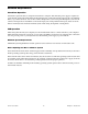
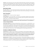
Chapter 2: Controls and Connections Top Panel Overview Phrase Arpeggiator buttons Gain controls Value control Performance controls Mode buttons LCD display Bank button Pitch Bend and Mod wheels Octave/Transpose buttons Multi Control buttons 49-key keyboard Figure 1. Venom top panel Gain Controls Master Volume Controls the master volume output from Venom. Synth Volume Controls the volume of the Venom synthesizer sent to the Master Volume (Main Outputs).
Inst Gain Controls the input gain of the audio signal from the Instrument Input. When the incoming signal is greater than –20 dB, the LED lights green to indicate the presence of an incoming audio signal on the Instrument Input. The LED lights red to indicate clipping. Adjust the Inst Gain level to the highest setting possible without clipping to get a good signal level for recording when using Venom with any audio recording software.
Performance Control Matrix The Performance Control Matrix lets you edit certain parameters of the synthesizer in real-time. This provides you with expressive control of the synthesizer during performance beyond simply playing preset synth sounds. Matrix Row Select Buttons and LEDs Use the Matrix Row Select buttons to select the next or previous Matrix row (1–6) as printed to the left of the Matrix Controller Knobs and Button.
Mode Buttons Multi Button Press the Multi button to enable Multi mode. The button lights when Multi mode is enabled. In multimode, Venom is multi-timbral and can play up to four Multi Parts (referencing Single Programs) at the same time. However, the 12 available voices are dynamically allocated from one Multi Part to another. Because the last note requested or played has the highest priority, new voices needed for other Multi Parts will be “stolen” from the oldest notes played in the original Multi Part.
Value Knob and Bank Button Value Knob By default, the Value knob lets you select any Venom Single Program, Mutli Program, or Pattern preset. While pressing and holding the Tap Tempo button, use the Value knob to set the tempo (in BPM, where the quarter note gets the beat). While pressing and holding both Octave buttons, the Value knob lets you change the transposition (+/–12 semitones).
In Enable mode, the LED lights to indicate that the associated part is enabled. Pressing any Multi Part button enables (or disables) the corresponding part. You can press more than one Multi Part button simultaneously to Select, Enable, or Mute (or deselect, disable, or unmute) those parts. When MIDI data is received on a part, the associated LED flashes briefly, regardless of the Multi Control mode.
Back Panel Controls and Connectors Mic Input Aux Inputs Left and Right Main Audio Outputs Left (mono) and Right Sustain Pedal Expression Pedal Instrument Input USB Port Power Switch DC Power Connector Kensington Lock Port MIDI Ports In and OUT Figure 3. Venom back panel Main Audio Outputs Connect the two 1/4” main audio outputs on the back panel to powered monitors, an am- plifier, or a mixer.
USB Port Connect this jack to any available USB port on your computer. The USB port handles all communi- cation between Venom and your computer. DC Power Connect the included power supply to power Venom. Power Switch This switch powers Venom on and off. Kensington Lock Port Connect a standard laptop-style locking security cable here to protect Venom from theft.
Chapter 3: Using Venom Standalone Making Connections This chapter covers the various hardware connections when setting up Venom. 1 Connect Venom to an AC outlet using the 9V power supply (included). 2 Connect the Main Outputs to either powered monitors, a mixer, or amplifier. You can also connect headphones to the front panel headphone jack. 3 Turn the Master Volume all the way down. 4 Set the back panel power switch to the “on” position.
Venom Audio Input Connections Venom provides audio input for external instruments and other audio sources. Use the Gain and Volume controls on the top panel of Venom to mix any incoming audio signals along with the synthesizer output. Figure 5 below shows one possible configuration for connecting the audio inputs and outputs for Venom: • Connect a dynamic Mic to the Microphone Input jack (TRS). Use the Mic Gain knob on the top panel to adjust the level.
Venom MIDI Connections Venom provides MIDI Input and Output ports to which you can connect a MIDI sound module or another MIDI controller. If you want to use another MIDI controller to play Venom, connect the MIDI Out port of your other MIDI controller to the MIDI In port on Venom. When you play your other MIDI controller, it will send MIDI to Venom and play the synthesizer.
Programs Venom provides 4 Banks of 128 Single Programs each and 2 Banks of 128 Multi Programs each. Banks A and B of the Single Programs are “Preset Programs,” and Banks C and D can be used for storing your own “User Programs.” Selecting Single Program Presets A Single Program stores and recalls all of the synthesizer parameter settings for a single sound, including the settings for its Insert Effect, 2 Global Bus Effects, the Main EQ, and one Arpeggiator Pattern.
Editing Multi Programs Each Multi Program references up to four different Single Programs. Each referenced Single Program in a Multi Program is referred to as a Multi Part. You can edit each Multi Part individually as well as in tandem. To select a new Single Program preset for a Multi Part: Switch Venom to Select Mode by repeatedly pressing the Mute/Enable/Select button until the Select LED is lit 1 2 Press the desired Multi Part button so that its LED is lit.
4 If desired, rename the Single Program: • Press the OCTAVE + button. In the Venom LCD, the first character of the program name starts flashing. • Use the Value knob to change the character. • Press OCTAVE + button to move to the next character to the right for editing. • Use the OCTAVE – button to move back to the next character to the left for editing. Press the Store button a second time to save the Single Program settings to the selected Bank and preset location.
Saving Multi Programs, Parts, and Patterns To save the current settings of a Multi Program: 1 Ensure that the Multi button LED is lit and that you have been editing a Multi Program. 2 Press the Store button. The Multi button and the Store button LEDs start flashing. 3 If desired, select a new storage location for the Multi Program: • Press the Bank button to select the Bank where you want to save the current settings for the Multi Program.
To save the current settings for multiple selected Multi Parts: 1 Ensure that your keyboard is in Multi mode. Press the Store button. The selected Multi Part buttons and the Store button LEDs start flashing. The LCD screen will ask “StoreWhat?” prompting you to select the Multi Parts you are storing. 2 You can exit Store mode without saving your changes by pressing one of the other unlit Mode buttons. 3 Press the Multi Part button you want to save.
7 Press the Store button to save the Multi Part Pattern settings to the selected Bank and preset location. To store additional Multi Part Patterns, ensure your keyboard is still in Multi mode, and repeat steps 2 through 7 until the “Edited” flag goes away. To save the only the current settings of a Multi after editing Multi Parts: Press the Store button. The Store button LED and the Multi Part button LEDs of any edited Multi Parts start flashing.
Using the Arpeggiator The Venom arpeggiator provides 3 modes: Standard, Phrase, and Drum. While these modes can only be edited via MIDI or software, you can select from the available factory patterns that use all of the various arpeggiator modes. For information on importing your own patterns, see “Pattern Import” on page 31.
6 Press the Bank button to select the Pattern Bank you want. 7 Use the Value knob to select the Pattern you want. If a Standard pattern is selected, play a single note or chord. If a Phrase or Drum pattern is selected, play a single note. 8 Enabling the Arpeggiator Every Single Program and Multi Patch is stored with an associated Arpeggiator Pattern, simply enable the Arpeggiator and play. To enable the Arpeggiator: 1 Select a Single or Multi Program.
Selecting MIDI Output In Single mode, Venom sends and receives MIDI data using the Global MIDI Channel. In Multi Mode, any Multi Part set to “Global” will also use the Global MIDI Channel for transmission. To select the global MIDI Output: 1 Press the Edit Button on the top panel of Venom. 2 Press the A-flat below middle C on the keyboard (indicated as “MIDI Out” by the Global Key Mapping above the keyboard). The LCD indicates either “MIDI OUT USB” or “MIDI OUT KEY” to indicate the setting.
Demo Mode Venom provides a factory demo. Press both the Pattern and Multi buttons at the same time to hear what Venom can do. During the demo, the LCD screen flashes “** DEMO **”. The Venom keyboard, and Pitch Bend and Modulation wheels are disabled during the demo. Press any button to stop the demo and return to the previous mode.
Chapter 4: Using Venom with USB Making Connections In addition to using Venom as a standalone synthesizer, you can use Venom with your computer via USB: • Connect the Audio Outputs to powered monitors, mixer, or amplifier. You can also monitor Venom using headphones connected to the jack on the front panel. • Connect Venom to your computer using the included USB cable. • Connect the power supply and power on Venom.
Configuring Venom on Mac Configuring Audio MIDI Setup (AMS) Once you have connected Venom to your Mac via USB and powered it on, you can configure the Audio MIDI Setup application to use Venom as an audio and MIDI interface. 1 Locate and launch the Audio MIDI Setup application (/Applications/Utilities/). 2 Select the Audio window (Window > Show Audio Window). 3 In the Audio Devices list, select Venom. 4 Click the Output tab and adjust the available output controls as desired.
For the device, Venom, MIDI port 2 (In and Out) corresponds to the physical MIDI In and Out ports on Venom. If you are configuring AMS to use Venom with a MIDI sound module, add a new Device in AMS, identify it as your MIDI sound module, and connect the MIDI In and Out ports of the module to the MIDI In and Out ports 2 of Venom. Audio MIDI Setup, new MIDI device connected to Venom Refer to your DAW documentation for information about additional configuration that maybe required.
Configuring Venom on Windows Windows XP To configure Windows XP to use Venom as the audio input and output device for your computer: 1 From the Start menu, choose Control Panel. 2 Double-click Sounds and Audio Devices. 3 Click the Audio tab. 4 From the Sound Playback Default Device pop-up menu, select Venom Out 1/2. 5 From the Sound Recording Default Device pop-up menu, select Venom In 1/2.
Configuring M-Audio Venom Properties The Windows control panel for M-Audio Venom properties provides controls for importing MIDI files for the Phrase Arpeggiator, and also provides access to information about and resources for Venom. The Windows control panel for M-Audio Venom also provides the Latency tab for controlling hardware buffering for audio with Windows class compliant audio drivers. To open the M-Audio Venom control panel: 1 From the Start menu, choose Control Panel.
Control Panel Pattern Import and About Pages Pattern Import To import a MIDI file for use with the Venom Phrase Arpeggiator: 1 Open the M-Audio Venom control panel. 2 Select the Pattern Import tab to show the Pattern Import page. M-Audio Venom Control Panel, Pattern Import page (Mac shown) Click the Browse button to navigate to and select a MIDI file. Note that the resulting pattern will be 8 quarter notes or 16 eighth notes.
Import Settings Adjust the Import Settings to match the MIDI file you want to import. Start Measure Lets you specify in which measure to start the pattern import. MIDI Channel Lets you specify the MIDI channel that the imported data is on. For example, if you are import- ing from a General MIDI sequence with drums on MIDI channel 10, you would need to select that channel number to import the drum part.
Web Links Knowledge Base Links to the M-Audio online knowledge base. Manuals Links to M-Audio documentation online. Registration Links to online product registration. Support Links to online support. Updates Links to the latest updates for M-Audio drivers and software. Using Venom with your DAW (Example Using Pro Tools M-Powered) Venom integrates seamlessly with your favorite digital audio workstation (DAW), such as Pro Tools, Logic, Cubase, or Ableton Live.
Recording MIDI from Venom Once you have installed the M-Audio Venom drivers, you can record MIDI from Venom in Pro Tools or use it to play virtual instruments in Pro Tools. Venom can send MIDI from the keyboard and top-panel controls, or it can pass MIDI through from the external MIDI In port on the rear panel (for example, if you are using an external controller with Venom, you can record that MIDI in Pro Tools too). To record MIDI from Venom in Pro Tools: 1 Create a new MIDI or Instrument track.
Playing Venom from MIDI in Pro Tools Once you have installed the M-Audio Venom drivers, you can send MIDI from a Pro Tools MIDI or Instrument track to play the Venom synthesizer. To play Venom from MIDI tracks in Pro Tools: Choose the MIDI track you just used to record MIDI from Venom (see “Recording MIDI from Venom” on page 34). 1 2 From the MIDI Output selector, select one of the following: • Venom USB Synth Out. Select this if you want to send MIDI to the synthesiser. • Venom USB MIDI Out.
Chapter 5: Advanced Synthesizer and Effects Editing Vyzex Venom Editor The Vyzex Venom Editor lets you can edit every available parameter in Venom Single and Multi Program patches. It also lets you edit Global parameters, manage patch banks, and configure Venom MIDI settings. When Venom is connected to your computer using USB, the Vyzex Venom Editor lets you program all of the parameters of Venom (including those not available from the top panel controls).
Vyzex Venom Editor Window The Vyzex Venom Editor window lets you access and edit various Venom controls and parameters from your computer. Figure 8.
Common Controls The Vyzex Venom Editor provides several common controls along the left side and on the bottom of the windows regardless of which Mode is selected. Specific controls for the selected Mode are available in the middle part of the window. These controls mirror the physical buttons and knobs on the top panel of Venom (see “Top Panel Overview” on page 5). Mode Use the Mode buttons to select a mode for editing (such as Multi or Single).
Store The Store button lets you save the current settings for the selected Pattern, or Multi or Single program. To save the current settings for the selected Pattern, or Multi or Single program: 1 Configure the settings for the selected Pattern, or Multi or Single program as desired. 2 Click the Store button. 3 From the Store To pane, select the Bank and Program number to which you want to save the current settings. Saving the current settings for the selected Multi program 4 Click Store.
Pitch Bend and Modulation The Pitch Bend and Modulation wheels Vyzex Venom provide the same functionality as the top panel controls (see “Pitch Bend and Modulation Wheels” on page 6). Performance Controls The Performance controls in Vyzex Venom provide the same functionality as the top controls (see “Performance Control Matrix” on page 7). When adjusting the Performance Controls for the selected Single Program, these controls override the corresponding Single Program Editor controls.
Single Program Editor The Single Program pages provide controls for editing Venom Single Program parameters. To view the Single Program Editor: Click the Single button so that the button’s LED is lit. Figure 10. Single Program, OSC Page To view different Single Program Editor pages: Click the OSC, LFO, MOD, or AUX button to view the corresponding page.
To select a Single Program for editing, do one of the following: Use the Bank Manager to select the Single Program preset you want (see“Bank Manager” on page 79). Selecting a Single Program using the Bank Manger – or – Do the following: • Right-click (or double-click) the Bank display and select Bank A, B, C, or D. • Right-click (or double-click) the Program Number display, select the Single Program you want from the list and click OK.
OSC Page The Oscillator (OSC) page of the Single Program Editor provides access to the Oscillator, Mix, Filter, Envelope, Voice, and Pitch controls for the selected Venom Single Program. Single Edit, OSC page controls Oscillator Controls Oscillator controls Oscillator 1 Oscillator 1 controls Oscillator 1 is the main oscillator.
Keytrack Lets you enable or disable key tracking for the oscillator. When Keytrack is enabled, the pitch of the oscillator is determined by the MIDI note number (before any alteration by the Coarse and Fine tuning settings). When Keytrack is disabled, the pitch of the oscillator is determined solely by the Coarse and Fine tuning settings and remains constant regardless of the MIDI note number. Coarse Adjusts the bipolar tuning of the oscillator from concert pitch (A = 440 Hz).
Oscillator 3 Oscillator 3 has all of the exact same parameters as Oscillator 2. Oscillator 3 controls Waveform Can be edited using NRPN 017CH (see “Oscillator 1” on page 43). Keytrack (See “Oscillator 1” on page 43.) Coarse Can be edited using MIDI CC 31 (see “Oscillator 1” on page 43). Fine Can be edited using MIDI CC 63 (see “Oscillator 1” on page 43). Osc2 Sync Synchronizes the waveform start of Oscillator 3 to the waveform start of OSC 1.
Mix Controls Mix controls The Mix section provides controls for mixing the relative volumes of the three oscillators, the amount of Ring Modulation of Oscillator 2 on Oscillator 1, and also any external input into Venom (such as a Microphone or Instrument) before the signal is fed into the Venom Filter. Osc1 Determines the level of Oscillator 1 that is mixed with other Pre-Filter audio sources and sent to the filter. The Mix Level for Oscillator 1 can be edited using MIDI CC 56.
Filter Controls The Filter section of Venom processes the combined output from the Oscillators section as well as any external audio input (as set in the Mix section). Filter controls Pre-Filter Boost Lets you boost the signal level fed from the Pre-Filter Mixer into the Filter stage. When set to 0, no boost is applied. When set to 127, a +24 dB boost is applied.
Envelope Controls Venom provides 3 separate envelope generators (EG). Envelopes are time based modulation sources that react to how the keys are played. All envelopes can be used as a modulation sources for a variety of destinations (see Modulation Matrix). EG 1 is “hard wired” to Amplitude and as such always effects Amplitude in addition to any other modulation destination to which it may be assigned. EG 2 is typically applied to the Filter and EG 3 is freely assignable using the Modulation Matrix.
Voice Controls Voice Mode Poly Voice Mode In Poly Voice mode, each note played on the keyboard or using MIDI triggers a voice, up to the limit of 12-voice polyphony. Voices continue to sound until their Amplitude Envelope releases to silence, or until they are stolen by new voice triggers according to voice allocation. If Unison Mode is enabled, the additional voices play in parallel to the original voices and follow the same envelope and pitch behavior, up to the limit of 12-voice polyphony.
Detune Detunes (0–100 cents) the layered notes up and down equally from a central position. Multiple voice pitches “fan out” within the detune range and are spaced equidistant from each other in order to maintain a correct pitch center. Transpose Transposes the currently selected Single Program up or down +/– 64 semitones. Fine Tune Transposes the currently selected Single Program up or down +/– 50 cents.
LFO Page The LFO page of the Single Program Editor provides access to the LFO, Amp Mod, Insert FX, EQ, Aux FX, Insert FX, and Master controls for the selected Venom Single Program. Single Edit, LFO page controls LFO Controls Venom provides three Low Frequency Oscillators (LFOs) as periodic modulation sources. Note that LFO 3 is monophonic (calculated across all voices), while LFOs 1 and 2 are polyphonic (calculated individually for each voice played).
You can change the Waveform for LFO 2 by adjusting the LFO 2 Shape knob on the top panel Performance Controls matrix (knob 3, row 5), or using MIDI CC 15. The Waveform for LFO 1 and LFO 3 can be changed using MIDI CC 87 and MIDI CC 85 respectively.
Auto Pan Adjusts the amount (0–100%) of the Auto Pan effect. Insert Effect The Insert Effect lies between the voice output of the synthesizer engine and the Bus Effect Send. The following effects are available: EQ Bandpass, Compressor, Auto Wah, Distortion, and Reducer. Select the desired effect from the Type selector. The controls for the selected effect are shown in the Insert FX section. Effects parameters can also be edited using MIDI NRPN messages.
Type Selects either a High-Pass or Low-Pass filter for the Auto Wah effect. Cutoff Determines the initial cutoff frequency (20 Hz–16 kHz) of the filter. Resonance Determines the resonance level (0–100) of the filter. Sensitivity Sets the amount (–100 to +100%) that the triggered envelope modulates the filter cutoff frequency, and is based on the amplitude of the input signal. Attack Adjusts the attack time (2 ms–2 sec) of the triggered envelope.
Channel The Channel controls provide output channel mixing controls for the currently selected Single Program. These settings are useful for balancing the effects and the direct synth signal for the Single Program, as well as providing output channel EQ. Channel controls Direct Sets the amount of dry (un-effected) signal for the currently selected Single Program. Aux 1 Determines the level of Aux 1 processing for the currently selected Single Program.
Volume The Master Volume gain stage follows the Master EQ. This gain stage lets you balance the volume of Single Programs to ensure that all of your Programs are of consistent volume. This is especially useful when using Multi Programs. The Master Volume gain stage is not accessible from the top panel hardware controls, and is controllable only over MIDI. MOD Page Mod Matrix The modulation matrix provides definable modulation routes drawing from a list of Modulation Sources and Destinations.
Table 7.
Destination Selects the Destination (see Table 9 below) of the modulation route. Table 9. Modulation Destinations Table 10.
Table 9. Modulation Destinations Mod 11 Amount NRPN0180H–NRPN018FH: 74 Mod 12 Amount NRPN0180H–NRPN018FH: 75 Mod 13 Amount NRPN0180H–NRPN018FH: 76 Mod 14 Amount NRPN0180H–NRPN018FH: 77 Mod 15 Amount NRPN0180H–NRPN018FH: 78 Mod 16 Amount NRPN0180H–NRPN018FH: 79 Amount Sets the amount of modulation (from –64 to +63). Since this control is bipolar, negative modulations can also be applied. The modulation amount can be edited using NRPN01C0H–NRPN01CFH.
Aux FX 1 Auxiliary Effect 1 controls Type Selects the effect algorithm for Aux Effect 1. The available algorithms are: • Plate Reverb • Room Reverb • Hall Reverb • Mono Echo • Stereo Echo • Mono 3/4 Echo • Stereo 3/4 Echo • Mono 4/4 Echo • Stereo 4/4 Echo • Mono Triplet • Stereo Triplet • Long Mono Delay • Long Ping Pong Delay Enable Enables (or disables) the selected effect algorithm for Aux Effect 1.
Pre Delay Determines the amount of time that elapses between the original audio event and the onset of re- verberation. Under natural conditions, the amount of Pre-delay depends on the size and construction of the acoustic space, and the relative position of the sound source and the listener. Long Pre-Delay settings place the reverberant field behind rather than on top of the original audio signal. Hi Damp Reduces the output of the higher frequencies of the effect.
Time Delay controls Tempo Sync Synchronizes the Delay Tap Time to the current Tempo setting. Time Sets the length of the Delay Tap Time (0–127). Aux FX 2 Aux 2 Effect controls Type Selects the effect algorithm for Aux Effect 2. The available algorithms are: • Chorus • Flanger • Phaser • Delay Enable Enables (or disables) the selected effect algorithm for Aux Effect 2.
LFO Rate Sets the LFO speed for the effect. Depth Sets the amount of LFO modulation for the effect. Arp The Arpeggiator controls determine how the Arpeggiator performs for the currently selected Single Program. Single Edit, Arpeggiator controls Arp Source The Single Program Arpeggiator lets you select Single (S) or Pattern (P) to use either the arpeggiator settings stored with the pattern or those stored with the Single Program.
Root Note Determines the root note reference (0–127, or C–2 to G8) for the pattern. The Root Note setting only applies when the Arpeggiator Mode is set to Phrase. The root note sets the relationship of the output MIDI data (from the selected Phrase Pattern) to the input note data. For example, if the Pattern MIDI note is C3, and the root note is a D3, playing G4 on the keyboard results the pattern playing back transposed down a whole step (F4).
Multi Program Editor The Multi Program pages provide controls for editing Venom Multi Program parameters. A Multi Program references up to 4 Single Programs (Multi Parts), each with individual Insert Effects and Arpeggiators, two global Aux Effects busses, and a Master EQ. The Single Programs (Multi Parts) and Arpeggiator Patterns are essentially sub-objects that are referenced by the Multi Program, and aspects of each sub-object may be overridden by the Multi parameters described in this section.
To select a Multi Program for editing, do one of the following: Use the Bank Manager to select the Multi Program preset you want (see“Bank Manager” on page 79). Selecting a Multi Program using the Bank Manger – or – Do the following: • Right-click (or double-click) the Bank display and select Bank A or B. • Right-click (or double-click) the Program Number display, select the Multi Program you want from the list and click OK.
Multi Part Selectors The Multi Part selectors provide the same controls as on the top panel of Venom (see “Multi Controls” on page 9). These controls are available regardless of which Multi Editor page is viewed. The interactive display to the left of the Multi Part Selector buttons is unique to the Vyzex Venom Editor. This interactive display lets you enable, select, and mute any of the four available Multi Parts.
PARTS Page The Parts page of the Multi Program Editor provides access to the MIDI Map, Parts, Auxiliary effects, and Master controls for the selected Venom Multi Program. Each Venom Multi Program can have up to four Multi Parts. Each Multi Part is made up of a Single Program, a set of Control options, Channel mix controls, MIDI Map and General settings, and an Arpeggiator. Each of the four parts provides the same set of controls, but the settings are unique to each part.
Note Range The Vyzex Venom Editor lets you enter the Min and Max note values for the Note Range for any Enabled Multi Part, either by typing the values or by clicking and dragging across the desired note range on the keyboard graphic. Min Sets the low key (MIDI note number) for the playable range of the selected Multi Part. Notes below this setting do not play. This can be especially useful for setting up keyboard splits.
Sustain Enables or disables Sustain Pedal control (MIDI CC 64) for the selected Multi Part. Expr Enables or disables the Expression Pedal control (MIDI CC 11) for the selected Multi Part. Keyb Enables or disables the Keyboard control (MIDI note numbers) for the selected Multi Part. MIDI Enables or disables the External MIDI Input for the selected Multi Part. This includes the USB input as well as the MIDI In jack.
IFX Type Lets you select the Insert Effect Type for the selected Multi Part (Off, EQ Bandpass, Compressor, Auto Wah, Distortion, or Reducer). Direct Sets the amount of dry (un-effected) signal for the currently selected Multi Part. Aux 1 Determines the level of Aux 1 processing for the currently selected Multi Part. You can change the send level to Aux 1 using the FX Send 1 Level knob on the top-panel Performance Control matrix (knob 3, row 6).
Octave Determines the number of octaves (–4 to +4) in which the arpeggiator plays notes. A setting of +1 means that the arpeggiator plays the keys that are held, then plays the same notes an octave higher. Negative settings make the arpeggiator play notes in octaves below the ones that are held. This parameter is disabled when the Arpeggiator Mode is set to Drum.
VOICE Page The Voice page of the Multi Program Editor provides access to the Voice and Channel controls for the enabled Multi Parts for the selected Venom Multi Program. Multi Editor, VOICE page controls Voice Controls The Voice controls let you set the Voice settings for each enabled Multi Part. These controls are only available for enabled parts. Each Multi Part provides the same Voice controls as Single Programs (see “Voice Controls” on page 49).
Channel Controls The Channel controls let you set the Channel settings for each enabled Multi Part. These controls are only available for enabled parts. Each Multi Part provides the same Channel controls as Single Programs (see “Channel” on page 55). Multi Editor, Multi Part Channel controls M (Use Multi Settings) Overrides the referenced Single Program Voice settings and uses the Multi Part Voice set- tings.
The Multi Part Arpeggiator controls let you select M (Use Multi Data), S (Use Single Data), or P (Use Pattern Data) for the selected Multi Part Arpeggiator. M (Use Multi Data) Lets you specify the Arpeggiator parameters for the selected Multi Part. When Use Multi Data is selected, the Multi Part settings override the settings stored with the referenced Single Program. S (Use Single Data) When selected, the Multi Part uses the Arpeggiator settings stored with the referenced Sin- gle Program.
AUX FX 2 The Aux FX 2 controls provide access to the controls for Auxiliary Effect 2 (see “Aux FX 2” on page 62). Master The Master controls provide access to the controls for Master EQ and Volume (see “Master” on page 55). Multi File Notes The Vyzex Venom Editor lets you store metadata for each Multi Program. This information is only saved with Vyzex Venom Editor files stored on your computer, this information is not stored on the Venom synthesizer.
Root Note Determines the root note reference (0–127, or C–2 to G8) for the pattern. The Root Note setting only applies when the Arpeggiator Mode is set to Phrase. The root note sets the relationship of the output MIDI data (from the selected Phrase Pattern) to the input note data. For example, if the Pattern MIDI note is C3, and the root note is a D3, playing G4 on the keyboard results the pattern playing back transposed down a whole step (F4).
MIDI Receive Clock Determines whether or not the Master Tempo synchronizes to external MIDI Clock. When set to On, the master clock always synchronizes to incoming MIDI clock pulses and stops if they are not present. When set to Off, the master clock is autonomous and runs based on the Tempo setting. When set to Auto, Venom looks for clock pulses to synchronize to within the supported tempo range, but if no external clock pulses are present, the master clock runs autonomously.
Bank Manager The Vyzex Venom Bank Manager lets you select the Bank and Program number for Single, Multi, and Pattern programs. Figure 12. Bank Manager window, Single Programs Select All Selects all Programs in all Banks. Deselect All Deselects all currently selected Programs in all Banks. Get Selected Gets the selected Programs from the Venom synthesizer. Sync Selected Sends the selected Programs from the Vyzex Venom Editor to the selected Programs on the Venom synthesizer.
Appendix A: MIDI Specifications MIDI Channel Messages * n: Channel 00h~0Fh 0~15 * vv: Value 00h~7Fh 0~127 * kk: Note No.
CTRL 31 Bn 1F vv OSC3 coarse tune (…52=16’… 64=8’ … 72=4’ … 84=2’…) CTRL 35 CTRL 41 Bn 23 vv Bn 29 vv Filter Cutoff fine Voice Detune fine (0=-0.5 Semitones … 64=no detune … 127=+0.5 Semitones) CTRL CTRL CTRL CTRL CTRL CTRL CTRL CTRL CTRL CTRL CTRL CTRL CTRL CTRL Bn Bn Bn Bn Bn Bn Bn Bn Bn Bn Bn Bn Bn Bn Wave-Shape level (PW) OSC3->OSC1 FM amount OSC1*OSC2 (Ring-Mod) mix level Startpoint Modulation Oscillator Drift External In Level Ext.
CTRL CTRL CTRL CTRL 98 99 100 101 Bn Bn Bn Bn 62 63 64 65 CTRL CTRL CTRL CTRL CTRL CTRL CTRL CTRL CTRL CTRL CTRL CTRL CTRL CTRL CTRL CTRL 103 104 105 106 107 108 109 110 111 112 113 114 115 116 117 118 Bn Bn Bn Bn Bn Bn Bn Bn Bn Bn Bn Bn Bn Bn Bn Bn 67 vv 68 vv 69 vv 6A vv 6B vv 6C vv 6D vv 6E vv 6F vv 70 vv 71 vv 72 vv 73 vv 74 vv 75 vv 76 vv CTRL 126 CTRL 127 vv vv vv vv Bn 7E 00 Bn 7F 00 NRPN fine NRPN coarse RPN fine RPN coarse Modulation Depth Node 1 Modulation Depth Node 2 (EG2 -> VCF Cutof
NRPN 010CH Bn 63 02, 62 0C, 06 vv Aux1 Reverb GateHoldTime / Delay Time NRPN NRPN NRPN NRPN NRPN NRPN NRPN NRPN NRPN NRPN NRPN Bn 63 02, 62 11, 06 vv Bn 63 02, 62 12, 06 vv Bn 63 02, 62 13, 06 vv Bn 63 02, 62 14, 06 vv Bn 63 02, 62 15, 06 vv Bn 63 02, 62 16, 06 vv Bn 63 02, 62 17, 06 vv Bn 63 02, 62 18, 06 vv Bn 63 02, 62 19, 06 vv Bn 63 02, 62 1A, 06 vv Bn 63 02, 62 1B, 06 vv Aux2 Aux2 Aux2 Aux2 Aux2 Aux2 Aux2 Aux2 Aux2 Aux2 Aux2 0111H 0112H 0113H 0114H 0115H 0116H 0117H 0118H 0119H 011AH 011BH Dela
NRPN 0158H Bn 63 02, 62 58, 06 vv NRPN 0159H Bn 63 02, 62 59, 06 vv Bit Reducer 0..12 Bits reduction = 16...4 Bit resolution (Ins Select=5 Destructive) Rate Reducer 0..
Modulation Matrix Access Message [H] NRPN 0180H NRPN 018FH MIDI [Hex] Bn 63 03, 62 00, 06 vv Bn 63 03, 62 0F, 06 vv NRPN 01A0H NRPN 01AFH Bn 63 03, 62 20, 06 vv Bn 63 03, 62 2F, 06 vv NRPN 01C0H NRPN 01CFH Bn 63 03, 62 40, 06 vv Bn 63 03, 62 4F, 06 vv Venom User Guide Description Set Modulation Target on Node 1-16: 0:LFO3 Rate, 1=Cutoff, 2=Pitch, 3=OSC1 Pitch, 4=OSC2 Pitch, 5=OSC3 Pitch 6=Amplitude, 7=FilterQ, 8=Ringmod, 9=ExtIn, 10=FM Amount, 11=OSC1 PWM, 12=LFO1 Rate, 13=LFO2 Rate, 14=OSC Detune, 1
Appendix B: System Exclusive Implementation SysEx Format The basic format of the Venom SysEx message is described in the table below: Data [H] F0 F7 Size (bytes) 1 5 1 3 Variable 1 1 Format Venom sends and responds to SysEx messages constructed using the following header: Data [H] 00 01 05 21 Description M-Audio Manufacturer SysEx ID Device Class ID Device ID Format The Command byte follows the header.
Format 00 01 02 03 04 05 06 07 08 09 0A 0B 0C 0D OE 0F 10 11 12 13 14 Function Edit Buffer Dump Single Patch Dump Multi Patch Dump Arpeg Data Dump Arpeg Pattern Dump Single Name String Multi Name String Arpeg Name String Edit Edit Edit Edit Edit Edit Edit Edit Edit Edit Edit Edit Edit Global Param Single Param Multi Param Multi Part1 Param Multi Part2 Param Multi Part3 Param Multi Part4 Param Effect Param Arpeg Single Param Arpeg Part1 Param Arpeg Part2 Param Arpeg Part3 Param Arpeg Part4
For example, to send an Arpeggiator Header block for the Multi Part1 Edit buffer, the SysEx string would be: Data [H] F0 00 01 05 21 02 00 09 00 F7 Description SysEx ID M-Audio Manufacturer SysEx ID Class ID Device ID Cmd ID = Write Data Dump Addr1 ID = Edit Buffer Dump Addr2 ID = Multi Part1 Buffer Addr3 ID = 0 (Not used) Variable length block, encoded using 7-bit system Checksum value End of SysEx ID Address Patch Format When Addr1 ID is 01~08 for accessing data dumps, Addr2 ID is used
Data [H] F0 00 01 05 21 02 0C 01 34 05 7F F7 Description SysEx ID M-Audio Manufacturer SysEx ID Class ID Device ID Cmd ID = Write Data Dump Addr1 ID = Multi Part2 Patch Param Addr2 ID = MSB of param 180 Addr3 ID = LSB of param 180 MSB 7-bits of data value LSB 7-bits of data value End of SysEx ID Since there is no check-sum needed for sending individual parameters, there is no need for the host program to send an ACK/NAK packet to confirm that the data was received OK.
In order to request that all Single string data is sent, the SysEx string would be: Data [H] F0 00 01 05 21 01 07 00 00 F7 Description SysEx ID M-Audio Manufacturer SysEx ID Class ID Device ID Cmd ID = Request Data Dump Addr1 ID = Arpeg Name Strings Addr2 ID = All Patches Addr3 ID = 0 (Not used) End of SysEx ID The initial SysEx response would take the format: Data [H] F0 00 01 05 21 02 07 01 00 F7 Description SysEx ID M-Audio Manufacturer SysEx ID Class ID Device ID Cmd ID = Write Data
In order to store the current Multi Edit Buffer into Bank B Program 40, the following would be sent: Data [H] F0 00 01 05 21 06 02 02 28 F7 Description SysEx ID M-Audio Manufacturer SysEx ID Class ID Device ID Cmd ID = Store Patch Addr1 ID = Multi Patch Addr2 ID = Bank B Addr3 ID = Program 40 End of SysEx ID When storing and recalling patches, Venom responds with ACK once the store/recall process completes.
NAK This flag is sent if a patch dump was received incorrectly. This will be the case if the checksum does not match or the number of bytes in the packet does not match the value defined in the length byte. The device responds by re-sending the last data packet. The device also sends this message upon receiving an incorrect data packet. After three consecutive attempts to receive a data packet have failed the device sends the Cancel Message.
D1 & D2: Are the two 7-bit data bytes for an event & contain the following values: Event Type Note Controller Pitch Bend D1 Note Num CC Num PB LSB D2 Velocity Value PB MSB The only other event type is the end marker, which is stored as a 32-bit 0 (0x00000000). The header data for a pattern is stored as a separate block of data (see “Arpeggiator Header Data Dump” on page 102). Arpeggiator Limitations: • Patterns are limited to being only 2 bars long. • Patterns must fit inside 1024 bytes.
00 16 00 17 00 18 00 19 00 1A 00 1B 00 1C 00 1D 00 1E 00 1F 00 20 00 21 00 22 00 23 00 24 00 25 00 26 00 27 00 28 00 29 00 2A 00 2B 00 2C 00 2D 00 2E 00 2F 00 30 00 31 00 32 00 33 00 34 00 35 00 36 00 37 00 38 00 39 00 3A 00 3B 00 3C 00 3D 00 3E 00 3F 00 40 00 41 00 42 00 43 00 44 00 45 00 46 00 47 00 48 00 49 ChanStrip [PART1].Pan ChanStrip [PART1].Direct ChanStrip [PART1].Aux1Send ChanStrip [PART1].Aux2Send ChanStrip [PART1].FX_Type KeyMap [PART1].Channel KeyMap [PART1].KeyLow KeyMap [PART1].
00 4A 00 4B 00 4C 00 4D 00 4E 00 4F 00 50 00 51 00 52 00 53 00 54 00 55 00 56 00 57 00 58 00 59 00 5A 00 5B 00 5C 00 5D 00 5E 00 5F 00 60 00 61 00 62 00 63 00 64 00 65 00 66 00 67 00 68 00 69 00 6A 00 6B 00 6C 00 6D 00 6E 00 6F 00 70 00 71 00 72 00 73 00 74 00 75 00 76 00 77 00 78 00 79 00 7A 00 7B 00 7C 00 7D PartMap [PART4].Program Transpose [PART4].CoarseTune Transpose [PART4].FineTune Transpose [PART4].VoiceMode Transpose [PART4].UnisonMode Transpose [PART4].UnisonCount Transpose [PART4].
00 7E 00 7F 01 00 01 01 01 02 01 03 01 04 01 05 01 06 01 07 01 08 01 09 01 0A 01 0B 01 0C 01 0D 01 0E 01 0F 01 10 01 11 01 12 01 13 01 14 01 15 01 16 01 17 01 18 01 19 01 1A 01 1B 01 1C 01 1D 01 1E 01 1F 01 20 01 21 01 22 01 23 01 24 01 25 01 26 01 27 01 28 01 29 01 2A 01 2B 01 2C ArpPatch [PART1].Pattern ArpData [PART1].ArpMode ArpData [PART1].NoteOrder ArpData [PART1].OctaveRange ArpData [PART1].BiPolar ArpData [PART1].LatchKeys ArpData [PART1].RootNote ArpPatch [PART2].Enable ArpPatch [PART2].
** KeyMap [part].CtrlEnable_f is a compilation of 6 bits with following values: Bit0: 1 = Flags that the Pitchbend wheel is enabled. Bit1: 2 = Flags that the Modulation wheel is enabled. Bit2: 4 = Flags that the Sustain pedal is enabled. Bit3: 8 = Flags that the Expression pedal is enabled. Bit4: 16 = Flags that the Keyboard is enabled. Bit5: 32 = Flags that the External MIDI Input is enabled. *** Off/On is determined by evaluating the CC value received. If the CC value is 63 or lower, the state is “Off”.
00 21 00 22 00 23 00 24 00 25 00 26 00 27 00 28 00 29 00 2A 00 2B 00 2C 00 2D 00 2E 00 2F 00 30 00 31 00 32 00 33 00 34 00 35 00 36 00 37 00 38 00 39 00 3A 00 3B 00 3C 00 3D 00 3E 00 3F 00 40 00 41 00 42 00 43 00 44 00 45 00 46 00 47 00 48 00 49 00 4A 00 4B 00 4C 00 4D 00 4E 00 4F 00 50 00 51 00 52 00 53 00 54 Oscillator [OSC3].Waveform Oscillator [OSC3].CoarseTune Oscillator [OSC3].FineTune Reserved.Data2 Lfo [LFO1].Waveform Lfo [LFO1].Rate Lfo [LFO1].Delay Lfo [LFO1].Attack Lfo [LFO1].
00 55 00 56 00 57 00 58 00 59 00 5A 00 5B 00 5C 00 5D 00 5E 00 5F 00 60 00 61 00 62 00 63 00 64 00 65 00 66 00 67 00 68 00 69 00 6A 00 6B 00 6C 00 6D 00 6E 00 6F 00 70 00 71 00 72 00 73 00 74 00 75 00 76 00 77 00 78 00 79 00 7A 00 7B 00 7C 00 7D 00 7E 00 7F 01 00 01 01 01 02 01 03 01 04 01 05 01 06 01 07 01 08 ModRoute [MOD2].Scaling ModRoute [MOD3].Scaling ModRoute [MOD4].Scaling ModRoute [MOD5].Scaling ModRoute [MOD6].Scaling ModRoute [MOD7].Scaling ModRoute [MOD8].Scaling ModRoute [MOD9].
01 09 01 0A 01 0B 01 0C 01 0D 01 0E 01 0F 01 10 01 11 01 12 01 13 01 14 01 15 01 16 01 17 01 18 01 19 01 1A 01 1B 01 1C 01 1D 01 1E 01 1F 01 20 01 21 01 22 01 23 01 24 01 25 01 26 01 27 01 28 01 29 01 2A 01 2B 01 2C 01 2D 01 2E 01 2F 01 30 01 31 01 32 01 33 01 34 01 35 01 36 01 37 01 38 01 39 01 3A 01 3B 01 3C Compressor.Gain Distortion.Type Distortion.Depth Distortion.PreGain Distortion.PostGain Distortion.HighCutoff BandPass.MidFreq BandPass.MidGain BandPass.MidQ Reducer.BitDepth Reducer.
01 3D 01 3E 01 3F 01 40 01 41 01 42 01 43 01 44 01 45 PatchName PatchName PatchName PatchName PatchName PatchName PatchName PatchName PatchName [1] [2] [3] [4] [5] [6] [7] [8] [9] 0 0 0 0 0 0 0 0 0 ~ ~ ~ ~ ~ ~ ~ ~ ~ 127 127 127 127 127 127 127 127 127 Effects and Mixer Data Dump When an Effects Edit buffer data is recalled the following data is sent as part of the SysEx: Parameters can also be individually updated using the appropriate address.
Arpeggiator Header Data Dump When an Arpeggiator Edit buffer data is recalled the following data is sent as part of the SysEx:Parameters can also be individually updated using the appropriate address. Addr [H] 00 00 00 01 00 02 00 03 00 04 00 05 00 06 00 07 00 08 00 09 00 0A 00 0B 00 0C 00 0D 00 0E 00 0F 00 10 00 11 00 12 00 13 Parameter Name ArpPatch.Enable ArpPatch.ArpSrc_f ArpPatch.Bank ArpPatch.Pattern ArpData.ArpMode ArpData.NoteOrder ArpData.OctaveRange ArpData.BiPolar ArpData.LatchKeys ArpData.
00 10 00 11 00 12 ModulationWheel CC UsbRecord_f MonoRecord_f 0 ~ 131 Off/On *** Off/On *** *** Off/On is determined by evaluating the CC value received. If the CC value is 63 or lower, the state is “Off.” If it is 64 or higher, the state is “On.
Appendix C: Compliance Information Environmental Compliance Disposal of Waste Equipment by Users in the European Union This symbol on the product or its packaging indicates that this product must not be disposed of with other waste. Instead, it is your responsibility to dispose of your waste equipment by handing it over to a designated collection point for the recycling of waste electrical and electronic equipment.
EMC (Electromagnetic Compliance) Avid declares that this product complies with the following standards regulating emissions and immunity: • FCC Part 15 Class A • EN55022 Class A • EN 55024 • AS/NZS CISPR 22 Class A • CISPR 22 Class A FCC Compliance for United States Radio and Television Interference This equipment has been tested and found to comply with the limits for a Class A digital device, pursuant to Part 15 of the FCC Rules.
Safety Compliance Safety Statement This equipment has been tested to comply with USA and Canadian safety certification in accordance with the specifications of UL Standards: UL60065 7th /IEC 60065 7th and Canadian CAN/CSA C22.2 60065:03. Avid Inc., has been authorized to apply the appropriate UL & CUL mark on its compliant equipment. Warning Japan PSE Safety Important Safety Instructions 1) Read these instructions. 2) Keep these instructions. 3) Heed all warnings. 4) Follow all instructions.
Index A Velocity Curve 77 Global mode 23 Global parameters 77 Global/Panic button 10 AMS (Mac) 27 Arpeggiator Drum 22 enabling 23 importing Patterns (Mac) 31 Multi Program 71 Phrase 22 selecting a pattern 22 Standard mode 22 Top Panel controls 22 audio input connecting 14 Audio MIDI Setup (Mac) 27 audio outputs 11 Auxiliary Audio Inputs 11 H Headphone jack 10 I Inst Gain 6 Instrument Input 11 K Kensington Lock Port 12 B L Bank button 9 LCD Display 8 LFOs 51 Local control turning on/off 23 Low Freq
O Aux effects 59 Insert Effect 53 LFO page 51 Multi Program Arpeggiator controls 71 Channel controls 70 Expression enable 70 External MIDI Input enable 70 Global Editor 77 Keyboard enable 70 Modulation enable 69 Multi Part pages 68 Pitchbend enable 69 Sustain enable 70 Multi Program Editor 65 Oscillator page 43 Pattern 76 Single Program Arpeggiator controls 63 Envelopes 48 Filter 47 LFO 51 Mod Matrix 56 Oscillator 2 44 Oscillator 3 45 Program Name files 42, 66 selecting for editing 42, 66 Voice modes 49 O
Avid Technical Support (USA) Product Information 5795 Martin Road Irwindale, CA 91706-6211 USA Visit the Online Support Center at www.avid.com/support For company and product information, visit us on the web at www.avid.