
User guide


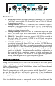
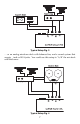


Back Panel
1. 9V AC Jack: This jack provides connection to the Super DAC’s external
"wall wart" power supply. The Super DAC uses a 9 Volt AC, 500 mA
(or more) power supply.
2.
Analog Out Left: The XLR (3 conductor) male connector outputs a
balanced, +4 dB (professional) level signal. The 1⁄4” jacks output an
unbalanced, -10 dB (semi-pro or consumer) line-level signal. Both
signals are output simultaneously.
3.
Analog Out Right: These XLR and 1⁄4” connectors output the right
side of the stereo signal in the same fashion as the Analog Out Left
connectors.
4. Digital In: Three digital inputs are present. AES/EBU is accepted at
the single male XLR connector, S/PDIF at the RCA jack, and optical
S/PDIF at the TOSLINK connector.
5.
AES/EBU GND lift: This switch is used to lift the digital ground
connection between the Super DAC and another AES/EBU device.
Typically the AES/EBU cable is connected to ground at the source end,
not the Super DAC end -- this prevents potential system ground loops;
therefore the factory default position is with ground lifted, with the
switch set to the left. Depending on the grounding configuration of
the connected device, sometimes you may get better performance by
not lifting the ground. The switch set to the right is the grounded
setting, with a diagram of the signal being sent to ground.
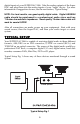
INSTALLATION
Along with this manual, your SUPER DAC 2496 contains a "wall wart" power
adapter with the specific voltage requirements needed to power the unit.
Using a different power adapter with different ratings could damage the unit
and void your warranty.
Plug the appropriate end of the power adapter into the Super DAC’s power
jack and the other end into a wall socket or power strip. Check to make sure
that the Super DAC and any other devices that you ar
e about to connect ar
e
turned off until all connections ar
e made.
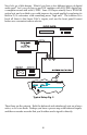
Now take the digital outputs of your sound "source" and plug them into the
4
➀ ➁ ➂ ➃ ➄