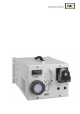
Operating Manual Gas conditioning unit Series CSS® Version CSS-M portable Gas sampling and gas conditioning technology 4-2.1.
List of Contents 1 General information ....................................................................................................................... 4 2 Declaration of conformity .............................................................................................................. 4 3 Safety instructions ......................................................................................................................... 5 4 Warranty .....................................................
Dear customer, we have made up this operating manual in such a way that all necessary information about the product can be found and understood quickly and easily. Should you still have any question, please do not hesitate to contact M&C directly or go through your appointed dealer. Respective contact addresses are to be found in the annexe to this operating manual. Please also contact our homepage www.mc-techgroup.com for further information about our products.
Head Office M&C TechGroup Germany GmbH Rehhecke 79 40885 Ratingen Germany Telephone: 02102 / 935 - 0 Fax: 02102 / 935 - 111 E - mail: info@mc-techgroup.com www.mc-techgroup.com 1 GENERAL INFORMATION The product described in this operating manual has been examined before delivery and left our works in perfect condition related to safety regulations. In order to keep this condition and to guarantee a safe operation, it is important to heed the notes and prescriptions made in this operating manual.
3 SAFETY INSTRUCTIONS Please take care of the following basic safety procedures when mounting, starting up or operating this equipment: Read this operating manual before starting up and use of the equipment. The information and warnings given in this operating manual must be heeded. Any work on electrical equipment is only to be carried out by trained specialists as per the regulations currently in force.
5 USED TERMS AND SIGNAL INDICATIONS DANGER! This means that death, severe physical injuries and/or important material damages will occur in case the respective safety measures are not fulfilled. WARNING! This means that death, severe physical injuries and/or important material damages may occur in case the respective safety measures are not fulfilled. This means that minor physical injuries may occur in case the respective safety measures are not fulfilled.
6 INTRODUCTION The portable unit CSS-M has been especially designed so that precise gas analyses can be carried out in any place. The entire gas conditioning unit is housed in a compact and robust steel plate case which ensures that the gas analyses can be carried out quickly, safely and with a minimum amount of maintenance.
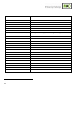
TECHNICAL DATA Portable Gas Conditioning Unit Type Sample outlet dew point Dew point stability Sample inlet temperature Gas inlet water vapour saturation Gas flow rate Ambient temperature Air humidity Storage temperature Pressure Total cooling capacity Number of gas inlets Number of gas outlets Sample gas connections Material medium-touched parts Ready for operation Mains power supply Power consumption Fuse protection Electrical mains supply Case protection Housing version Case dimensions (H x W x D) We
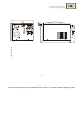
DESCRIPTION Figure 2 shows the dimensions and construction of the portable case. 220 17 300 Figure 2 47,5 Dimensions CSS-M Fine filter FPF-2-0,3GF Electronic controller Flow meter FM40 with sample gas outlet Peristaltic pump SR25.2 with condensate outlet Pump switch LED indication condensate alarm red Sample gas inlet All components of the gas conditioning unit are mounted in a portable sheet steel case.
RECEIPT OF MARCHENDISE AND STORAGE The portable gas sampling system CSS-M is a completely pre-installed unit. The scope of delivery includes furthermore: 25 Filter elements (1 pckg.
12 SUPPLY CONNECTIONS 12.1 HOSE CONNECTIONS 220 Sample gas outlet Sample gas inlet 0 177 Condensate outlet Figure 3 Hose connections CSS-M portable Do not mix up the hose connections; the connections are marked accordingly in figure 3. NOTE! After having connected all lines, please check the seals. All hose connections are DN4/6mm sealing ring threaded hose couplings out of PVDF/PPH as standard. They are suitable for gas inlet temperatures of maximum 80°C (see chapter 8).
WARNING! 12.2 Aggressive condensate is possible. Wear protective glasses and proper protective clothing! ELECTRICAL CONNECTIONS WARNING! NOTE! False supply voltage can damage the equipment.
After the starting time (LED K1 on the controller is beaming), the portable gas conditioning system is ready for use, and the sample gas pump is switched on provided the key is activated (shines green). The sample gas must not be fed before the starting time of the sample gas cooler is finished, i.e. if the sample gas outlet temperature does not exceed the limits adjusted at works (LED K1 on the controller is beaming).
Figure 4 14 Electronic board CSS-M.. CLOSING DOWN The location for the portable gas conditioning unit must remain frost-free, even if the unit has been switched off. NOTE! There are no special regulations to be observed if the portable gas conditioning unit CSS-M is to be closed down for a short period of time. In case of a long-term closing down, for example after a series of measurements has been completed, it is recommended to purge the gas conditioning system with ambient air or inert gas.
MAINTENANCE Before carrying out any maintenance work, the specific safety instructions referring to the instalment and the process must be observed! WARNING! Dangerous voltage. Before any maintenance work is carried out on the portable gas conditioning system, put the main switch of the instrument into position “0” and tear the mains plug off! The frequency of the maintenance work depends on the operational process and can therefore only be determined in each individual case.
O-ring Filter element Figure 5 15.2 Replacement of the filter element and the O-ring DISMOUNTAGE OF THE SAMPLE GAS PUMP FOR EXAMINATION OR MAINTENANCE For dismounting the sample gas pump N3 KPE: 15.
Figure 6 Replacement of the pump hose Disconnect the portable gas conditioning system from the mains voltage; Loosen the hose connections on the pump; Press the moving strap on the recessed grips and turn the S-bar clockwise as far as the limit stop; Take out the moving strap and pull the old pump hose on the hose nozzles out of the guides; Press the pressure rollers and check whether there is any tension on the springs, if not, exchange the pressure springs (see chapter 15.3.
Figure 7 Disassembly of pump head and driver Draw the pump head out of the motor shaft Take driver out of the pump head The removal of the springs (4 pcs.) away from the driver is easily possible without the aid of any tools. For this take spring out of the groove near to the shaft bore. Dismount roller axes and change contact pulleys. Take care that axes are not worn out by the springs and have damaged the dent at the axes front end.
Make sure that contact pulleys roll easily on the axis. After remounting the axis with contact pulley into the driver the spring has to be mounted as shown in Figure 8. Please pay attention to the alignment of the dent. Remounting happens in reverse order. NOTE! While mounting pay attention to the fit of ‘rotational axisdriver’ and check that the plunged boss at the shaft bore points to the front of the pump head. Use genuine spare parts only ! 15.3.
Figure 9 16.1 Front view of the temperature regulator CHANGING THE SET VALUE For changing the set value, you must press the P-button < 2s. The set value adjusted at the factory at 5°C is shown. With both arrow keys, the set value can be set upwards or downwards. However, this value should not be adjusted below +1°C, otherwise you must expect a freezing up of the heat exchanger. If you set the value above the ambient temperature, the cooler will not work.
17 TROUBLE SHOOTING The following table shows possible sources of errors and how to remove them (not applicable for the starting-up phase). Display Possible cause Examination/Correction None Fault No supply voltage; Check the supply voltage according to the type plate; ok? Control whether the mains plug is put in correctly or whether the main switch is in position „1“; ok? Examine the fine fuses F1, F2 on the internal board; ok? LED K1 is beaming permanently and temp.
Sample line to the analyser clogged or squeezed; Pollution of the diaphragm pump; Temp. <2°C 22 Cooler switches the sample gas pump automatically off; Cooler defective; No gas flow? Loosen the outlet hose on the analyser side and check on the threaded hose coupling whether sample gas flows; Sample gas does not flow? Clean the clogged line or replace it; Sample gas flows? ok? Loosen the piping on the pump head and examine it (see 15.
18 SPARE PART LIST Wear, tear and replacement part requirements depend on specific operating conditions. The recommended quantities are based on experience and are not binding. Portable Gas Conditioning Unit Version CSS-M (V) Consumables, (E) Recommended Spare Parts and (T) Spare Parts Recommended quantity after operation of [years] Part No. Description V/E/T 1 2 3 Fine filter FPF-2-0,3GF 90 F 0160 Filter element type F-2-0,3GF. Material: glass fiber, porosity: 0,3µ 25 pcs./pack.
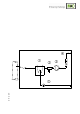
19 APPENDIX Circuit diagram CSS-M For further product documentation, please see our internet catalogue: www.mc-techgroup.com Instruction manual peristaltic pump SR25.1, SR25.1-G, document : 3-7.1-ME Instruction manual diaphragm pump series N document : 6-1.2.1-ME Flowmeter FM 40, document : 5-6.1.10 Liquid alarm sensor LA1..., document : 5-5.1.1 24 Gas sampling and gas conditioning technology 4-2.1.
Figure 10 4-2.1.