Operating Manual 19 Inch Rack Mounting Gas Conditioning Unit series CSS ® (incl. the new temperature controller type 70304) Gas sampling and gas conditioning technology 4-1.
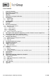
List of contents 1 2 3 4 5 6 General information ................................................................................................................... 5 Declaration of conformity .......................................................................................................... 5 Safety instructions ..................................................................................................................... 6 Warranty .........................................................
List of illustrations Figure 1 Figure 2 Figure 3 Figure 4 Figure 5 Figure 6 Figure 7 Figure 8 Figure 9 Figure 10 Figure 11 Figure 12 Figure 13 Figure 14 Figure 15 Figure 16 Front view of the CSS ...................................................................................................... 10 Operation and control board............................................................................................. 11 Plan view of the components mounted on the Flow components sub panel ..............
Dear customer, we have made up this operating manual in such a way that all necessary information about the product can be found and understood quickly and easily. Should you still have any question, please do not hesitate to contact M&C directly or go through your appointed dealer. Respective contact addresses are to be found in the annexe to this operating manual. Please also contact our homepage www.mc-techgroup.com for further information about our products.
Head Office M&C TechGroup GmbH Rehhecke 79 40885 Ratingen Germany Telephone: 02102 / 935 - 0 Fax: 02102 / 935 - 111 E - mail: info@mc-techgroup.com www.mc-techgroup.com 1 GENERAL INFORMATION The product described in this operating manual has been examined before delivery and left our works in perfect condition related to safety regulations. In order to keep this condition and to guarantee a safe operation, it is important to heed the notes and prescriptions made in this operating manual.
3 SAFETY INSTRUCTIONS Please take care of the following basic safety procedures when mounting, starting up or operating this equipment: Read this operating manual before starting up and use of the equipment. The information and warnings given in this operating manual must be heeded. Any work on electrical equipment is only to be carried out by trained specialists as per the regulations currently in force.
5 USED TERMS AND SIGNAL INDICATIONS DANGER! This means that death, severe physical injuries and/or important material damages will occur in case the respective safety measures are not fulfilled. WARNING! This means that death, severe physical injuries and/or important material damages may occur in case the respective safety measures are not fulfilled. This means that minor physical injuries may occur in case the respective safety measures are not fulfilled.
6 INTRODUCTION This M&C unit provides completely pre-installed sample gas conditioning for continuous use and can be excellently integrated within analysis systems.
7 TECHNICAL DATA Gas flow rate** Flow meter Gas pressure Sample inlet temperature** Sample inlet dew point** Sample outlet dew point Dew point stability Gas filter F-0,1GF50 Ambient temperature** Storage temperature Relative humidity Housing Degree of protection Weight Connections Power supply Electrical connection Warm up time Material of sample contacting parts Status signal for Test gas inlet - 2 x Option: Electronic PID temperature controller for heated sample lines Electrical equipment standard
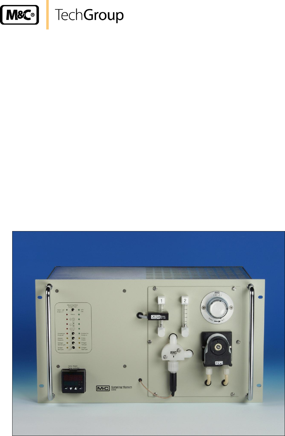
8 DESCRIPTION The components of the M&C gas conditioning sampling system type CSS are mounted in a 19" rack housing. The CSS may also be configured with an optional wall-mounting-bracket (Part-No. 03G9005). (1.4) (1.1) 1 (1.2) 1.2.6 1.2.1 483 465 1.2.
Figure 2 shows the operation and control board (1.1). The different functions are selected by toggle switches and indicated with LED’s. The internal or external function is configured through the wiring in the Sub-D-Plug (see 4.1) and indicated by a dual coloured LED on the operation and control board. Figure 2 Operation and control board Gas sampling and gas conditioning technology 4-1.
The following chart describes the functions of the operation and control board. Function Local Control (intern) Switch l r LED control of the CSS with operation and control board; link between pin 1 and 9 (connector X2, s. 10.2.2); control power supply; (dual coloured) green External Control external control with Sub-D-Plug X2 (s. 10.2.
All of the maintenance components are mounted on the flow components sub panel (1.2) (s. Fig. 1 and 3) and are easily accessed by removing front panel mounting screws. These are: (1.2.1) Gas-Filter FPF-0,1GF; (1.2.2) Peristaltic pump SR25.1; (1.2.3) Liquid-Alarm-Sensor LA1 with Flow-Chamber LS; (1.2.4) Flow-Meter 1 FM40, measuring range 7-70l or 25-250l** (1.2.5) Optical bi stable Flow-Alarm-Sensor FA-1,bi; (1.2.6) Flow-Meter 2 FM40, measuring range 7-70l or 25-250l**; (1.2.
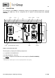
5 10 24 13 15 19 Schnitt A-A 14 6 16 265 17 8 23 9 20 21 1.2 Figure 4 Components mounted in the 19“ rack housing The gas cooler (10) is fixed on the back panel of the 19“ rack housing. With respect to the maximum flow rate required, the following versions are available: Cooler ECP 1000 ECP 2000 ECP 3000 max. flow rate [l/h] 140 2 x 140 350 Ambient air enters the chassis through the slots in the bottom (8) and top plate (9) of the 19“ rack housing.
All the electrical and tube-/hose connections are located on the back panel of the 19" rack housing. These are: (A) Sub-D-Plug X2 (see 10.2): - external status inquiry device status measuring/test mode - control functions internal ( the link between pin 1 and 9 is factory installed and must exist for the local control to function) external (with potential free contacts) (A1) Reserve (B) electrical junction box X1 (see 10.
9 FUNCTION The gas flow schematic of the CSS is shown in the following illustration. 2 1 D CSS; CSS-3 C 3 7 4 9 10 E K M 12 13 B2 FM1 FM2 L CSS-2 C 11 4 7 9 Y1 E1 B1 Y1 M1 5 6 Y2 Y3 G F Zero gas 1 E1 FI1 8 M1 H A B Span gas 2 D CSS/C; CSS-3/C with option 03G9030 (a) C B1 E 12 13 B2 9 7 4 3 Y1 FM1 10 E1 J B1 M1 I 6 5 Y2 F 14 FM2 11 6.1 Y3 Y4 K G 15 6.2 15.1 Y6 N 15.2 8 6.3 Y5 L Fl1 M2 H A B 15.
The peristaltic pump (8) draws and removes the condensate via the condensation outlet (H) on back panel. The liquid alarm sensor (9) which located after the gas cooler protects the gas analysers in the event of faulty gas drying. In the event of an alarm in the condensate removal, cooling or heating functions, the 3-way solenoid valve is automatically closed. Also the measuring pump is switched off so that no wet gases can reach the gas outlets (D) and (E).
10 ELECTRICAL CONNECTIONS The electrical connections are located on the back panel of the 19“ rack housing (see fig.5) 10.1 ELECTRICAL JUNCTION BOX X1 Figure 7 shows the possible connections of the electrical junction box X1 (B).
10.2 SUB-D-PLUG X2 To guarantee the function of the CSS, the SUB-D-Plug must be mounted! NOTE! 10.2.1 STATUS CONTACTS Two potential free switches operating in ‘Safety-First’ function and guarantee an adequate signal for CSS being in test mode, alarm mode or loosen voltage. For one of the above mentioned situations the circuit is closed by the contacts MC (master contact, 5 and 15) ) and NC (normal closed, 7 and 14).
10.2.2 LOCAL CONTROL For local control all functions of the CSS are effected by the operation and control board (functions see 8.). NOTE! For local control, the link between PIN 1 and 9 in the SUB-D-Plug is necessary! The way for gas to enter the CSS is chosen by operating the adequate switch on the operation and control board (see 8.). All other possible gas ways will be automatically closed. This avoids measuring inaccuracy by simultaneous feeding the CSS with different gases. For version CSS...
10.2.3 EXTERNAL CONTROL The external control off the CSS has to be realised by customer by means of potential free switches. The selector switch functions of the control board (s. 8.) are out of operation. NOTE! For external control, the link between PIN 1 and 9 in the D-SUB-Plug must be removed! Operating error by feeding the CSS simultaneous with sample- and test gas must be excluded by customer! Figure 10 Plan of terminal connections in the D-Sub-Plug X2 (A) for external control of the CSS...
10.3 LIQUID- AND FLOW ALARM CARD LFC-2 The LFC-2 is a combined electronic card operating the flow alarm sensor FA1bi and the liquid alarm sensor LA1. Pulsating gas flow can release a unintentional flow alarm. To avoid this the LFC-2 is equipped with slow operation -time lag to eliminate the alarm- and slow release -alarm with time lag. Times in between 3 and 13 seconds (3 seconds are factory-aligned) are continuously adjustable by the potentiometers P5 and P6 (see Fig. 11, wiring diagram LFC-2).
From Version 03.2000 Figure 11 Circuit diagram LFC-2 Gas sampling and gas conditioning technology 4-1.
11 DESCRIPTION OF THE OPTIONAL TEMPERATURE CONTROLLER 70304 FOR HEATED SAMPLE LINES (1) Actual value display (4) PGM-key in order to select parameters in order to change values red, 10mm high, 4 digits in order to change values (2) Active Setpoint (5) Factory setting SP1 (3) Setpoint Four digit, green; decimal place is configurable; Also used for operator prompting (display of parameter and level symbols) (6) Exit-key in order to leave the levels Indication yellow for - Switch status o
Function of the controller Fnct, factory setting = 0 : fixed-setpoint controller. Other values are not adequate for the operation of M&C products. Sensor type SenS, factory setting = 2: Resistance thermometer in 2-wire circuit 1: Resistance thermometer in 3-wire circuit 2: Resistance thermometer in 2-wire circuit 4: Thermocouple Linearization Lin, factory setting = 1, Pt100 1: Pt100 9: Fe-CuNi J 11: Fe-CuNi L 12: NiCr-Ni K Further information is in the separate manual 2-5.1.
13.2 MENUE STRUCTURE Generally: Changing to the user level with PGM-key (display = User) To choose the first parameter press PGM-key again (display = SP) Changing to the next parameter with -key Back to the standard display press EXIT-key (2x) SP (ALSE = = Lo-t (LFun tion) Fnct (rASL SenS Lin = = Setpoint Excess temperature with lock) Low temperature alarm Limit comparator func- = = = = Function of controller Ramp slope) Sensor type Linearization Standard display 290 .
14 RECEIPT OF GOODS AND STORAGE The CSS is completely pre-installed and normally delivered in one packaging unit. Please take the gas conditioning system and possible special accessories carefully out of the packaging material immediately after arrival, and compare the goods with the items listed on the delivery note; Check the goods for any damage caused during delivery and, if necessary, notify your transport insurance company without delay of any damage discovered.
16 SUPPLY CONNECTIONS 16.1 HOSE CONNECTION NOTE! The CSS is equipped with G1/4“i connections. Do not mix up the hose connections: they are clearly marked. After all the hoses have been connected, the tightness of such leads should be checked. Connection hoses with dimensions DN 4/6mm are utilised for all models. The following lines have to be connected (Fig.
NOTE! For the erection of power installations with rated voltages up to 1000V, the requirements of VDE 0100 and relevant standards and specifications must be observed! The main circuit must be equipped with a fuse corresponding to the nominal current (over current protection); for electrical details see technical data. Connect power supply (optional heated sample line with temperature sensor) to the corresponding terminals of the electrical junction box X1 (Fig.
NOTE! Adjust the flow meter FM1 to a flow rate above the demanded alarm value. Because of breaking the outlet dew point (5°C) the total flow rate should not pass the specified maximum value (see 2.). The minimum flow rate is determined by the sample gas pump. This requires the following minimum values: N3 KPE: approx. 60l/h; N9 KPE: approx. 200l/h; If the flow rate remains under the minimum value the pump membrane can be premature destroyed by over pressure ! 17.
17.3 SELF-OPTIMISING (PID-FUNCTION) OF THE CONTROLLED SYSTEM The controller type 70304 has the possibility of a self-optimisation-function if it operates as a PIDcontroller. In all M&C components this function is pre-adjusted. This means that a self-optimisation is necessary starting up the component. NOTE! WARNING! For self-optimising of the control circuit, the heating of the heated sample line must be connected to the appropriate terminals of the CSS (s. 10.1).
19 MAINTENANCE Before the maintenance work is carried out, it is necessary that the specific safety procedures pertaining to the system and operational process be observed! WARNING! Dangerous voltage. It is necessary to take the equipment off the mains before any assembly, maintenance or repair work is carried out.
WARNING! Aggressive condensate is possible.
21.2 COOLER ALARM/TEMPERATURE CONTROLLER ALARM Cooler alarm is released if the cooler temperature is <2°C or >8°C, also in the period till the CSS is ready for operation. As well cooler alarm is released if the temperature controller (option) of the heated sample line is out of range. The operative cooler/temperature controller opens the 3way solenoid valve and makes the function ‘Pump On’ possible. For alarm elimination please check: the function of the cooler; see separate manual 3-1.
21.4 LIQUID ALARM The M&C liquid sensor alarm unit LA1 is useful whenever liquid can damage a gas analyser system. This may occur if a gas dryer unit or a drain system fails. The M&C LA1 liquid sensor is constructed in the following way that any droplets of liquid in the sample gas are attracted under gravity to the sensor surface and even the smallest liquid droplets trigger a sure and rapid alarm.
22 SPARE PART LISTS Wear, tear and replacement part requirements depend on specific operating conditions. The recommended quantities are based on experience and are not binding. 19“ GAS CONDITIONING UNIT TYPE CSS... (C) consumable parts, (R) recommended spare parts, (S) spare parts Artikel-Nr. Bezeichnung C/R/S recommended quantity in operation [years] 1 2 3 Cooler ECP-1000/ECP-2000, ECP-3000: 10 (s. Fig.
19“ GAS CONDITIONING UNIT TYPE CSS... (C) consumable parts, (R) recommended spare parts, (S) spare parts C/R/S recommended quantity in operation [years] 1 2 3 Flowmeter FM40: 1.2.4 (s. Abb.3) 90 A 0015 94 F 0015 90 A 0018 09 F 4000 09 F 4010 Flow meter glass for FM40 range 7-70 l/h air for version CSS... and CSS.../C Flow meter glass for FM40 range 25-250 l/h air for version CSS... and CSS.../C Viton O-ring 9 für flow meter glass Flow meter FM40 7-70l/h (compl.), for versions CSS... und CSS...
23 APPENDIX Pin assignment for external drive of the CSS Circuit diagram gas conditioning CSS, drawing number : 2443-5.01.5; CSS wit 4 x span solenoid valves, drawing number : 2443-5.03.0; For further product documentation, please see our internet catalogue: www.mc-techgroup.com Instruction manual electric gas cooler ECP 1000/2000/3000, document : 3.1.1-ME Instruction manual peristaltic pump SR25.1, SR25.1-G, document : 3-7.1-ME Instruction manual diaphragm pump series N document : 6-1.2.
CSS Ansteuerung von Extern CSS controlling external Prüfen NC Check NC Prüfen NO Check NO Status MC Status MC Prüfgas über Sonde nur bei Option CSS-C Cal. gas to the probe only by option CSS-C Nullgas EIN Zero gas ON Meßgas EIN Sample ON +15V +15V Achtung! Bei Steuerung intern ist die Brücke 1-14 im Dsub-Stecker unbedingt erforderlich. * Attention! For function intern the link between pin1 and 14 in the Dsub-plug is necessary.
Figure 15 Circuit diagram gas conditioning CSS Gas sampling and gas conditioning technology 4-1.
Figure 16 CSS with 4 x span solenoid valves Gas sampling and gas conditioning technology 4-1.