
Operator's manual


14
Gas sampling and gas conditioning technology 4-1.1-ME
265
6
23
5
9
8
14
10 13
2120
Schnitt A-A
16
17
15 1924
1.2
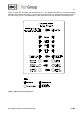
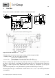
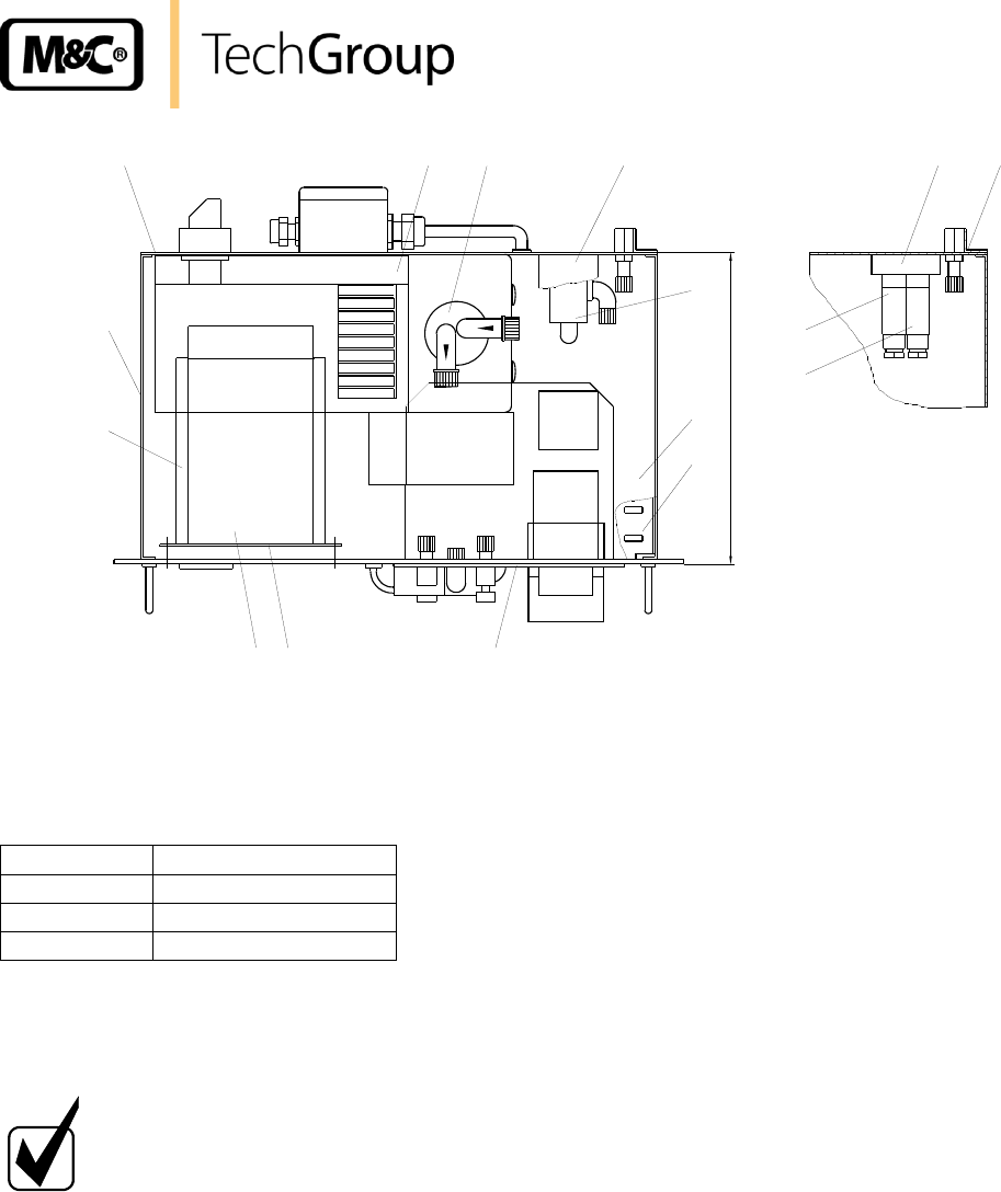
Figure 4 Components mounted in the 19“ rack housing
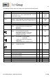
The gas cooler (10) is fixed on the back panel of the 19“ rack housing. With respect to the maximum
flow rate required, the following versions are available:
Cooler
max. flow rate [l/h]
ECP 1000
140
ECP 2000
2 x 140
ECP 3000
350
Ambient air enters the chassis through the slots in the bottom (8) and top plate (9) of the 19“ rack
housing. This allows ventilation and cooling of the internal components including the gas cooler.
The cooler fan exhausts air out of the cut out in the side wall (6) of the 19“ rack housing.
NOTE!
The PSS must be stored in a weather-protected frost-free area ! Allows ade-
quate ventilation around the chassis !
The 3-way solenoid valve (14), for switching of the sample and test gas, is mounted in a special holder
(13) on the back panel (5).
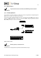
Sectional view A-A in illustration 4 shows the two 2-way solenoid valves (16) and (17), for zero and
span gas. They are mounted with valve block (15) below the valve (14) on the back panel of the 19"
rack housing. Additional 3 span gas valves are possible as option (see page 8). The span gas valves
are preselected by snap switch 1.5 (Fig. 1).
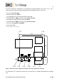
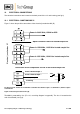
The combined card for flow- and liquid alarm LFC-2 (20) is connected on the main circuit board (21).
The CSS is protected by fuse (F1= 2A, see wiring diagram in appendix).