Operating Manual Gas conditioning unit Series CSS® Version CSS-V1 and CSS-V2 for 19“- or wall mounting Gas sampling and gas conditioning technology 4-1.
List of Contents 1 2 3 4 5 6 7 8 General information ....................................................................................................................... 4 Declaration of conformity .............................................................................................................. 4 Safety instructions ......................................................................................................................... 5 Warranty ............................................
Dear customer, we have made up this operating manual in such a way that all necessary information about the product can be found and understood quickly and easily. Should you still have any question, please do not hesitate to contact M&C directly or go through your appointed dealer. Respective contact addresses are to be found in the annexe to this operating manual. Please also contact our homepage www.mc-techgroup.com for further information about our products.
Head Office M&C TechGroup Germany GmbH Rehhecke 79 40885 Ratingen Germany Telephone: 02102 / 935 - 0 Fax: 02102 / 935 - 111 E - mail: info@mc-techgroup.com www.mc-techgroup.com 1 GENERAL INFORMATION The product described in this operating manual has been examined before delivery and left our works in perfect condition related to safety regulations. In order to keep this condition and to guarantee a safe operation, it is important to heed the notes and prescriptions made in this operating manual.
3 SAFETY INSTRUCTIONS Please take care of the following basic safety procedures when mounting, starting up or operating this equipment: Read this operating manual before starting up and use of the equipment. The information and warnings given in this operating manual must be heeded. Any work on electrical equipment is only to be carried out by trained specialists as per the regulations currently in force.
5 USED TERMS AND SIGNAL INDICATIONS This means that death, severe physical injuries and/or important material damages will occur in case the respective safety measures are not fulfilled. DANGER! WARNING! This means that death, severe physical injuries and/or important material damages may occur in case the respective safety measures are not fulfilled. This means that minor physical injuries may occur in case the respective safety measures are not fulfilled.
6 INTRODUCTION The gas conditioning unit CSS-V.. for wall- or 19”-mounting is a completely pre-assembled compact gas conditioning system, working continuously and delivering a sample gas quantity of max. 2 x 150Nl/hr resp. 1 x 250Nl/hr. A big variety of additional options guarantees an adaption to the different requirements of continuous gas analysis technique.
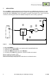
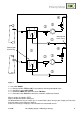
7 APPLICATION The units CSS-V.. provide completely pre-installed sample gas conditioning for continuous use and can excellently be integrated into gas analysis systems. Its compact construction means that it takes up only little space. The CSS-V.. units are ready for use within a few minutes. This, at last, makes the usual time-consuming procurement of individual components and assembly superfluous. Figure 1 Scheme of gas flow CSS-V1..
Marking with black o-ring Marking with black o-ring Figure 2 Scheme of gas flow CSS-V2.. Gas cooler ECM-2 2 x Front panel filter FPF-2-0,3GF, 0,3µm porosity with integrated liquid alarm 2 x Sample gas pump N3/5/9 KPE 2 x Flowmeter FM40 with option flow alarm FM-20mo 2 x Peristaltic pump SR25.2 for continuous automatic condensate removal Way of sample gas tubed in PTFE. Way of condensate tubed in Novopren®.
8 TECHNICAL DATA Gas Conditioning Unit Type Part No. 230V/50Hz Part No.
8.1 OPTIONS Part No. 93 K 0140 93 K 0170 93 K 0160 97 K 0100 97 K 0110 97 K 0115 01 G 6125 01 G 6130 01 G 6135 01 G 6120 09 F4000 09 F 4005 09 F 4010 02 E 3500 01 G 6150 01 P 9125 4-1.
9 DESCRIPTION Figure 3 Design CSS-V2.. Fine filter FPF-2-0,3GF Electronic controller Flow meter FM40 with flow alarm sensor FA-20mo Peristaltic pump SR25.2 with condensate outlet Cold appliance socket Connection for summery alarm Sample gas outlets Condensate outlet directly at the peristaltic pump Sample gas inlet directly at the heat exchanger All components of the gas conditioning unit are mounted in a compact sheet steel case.
The DN4/6mm hose connections for the sample gas outlet as well as the electrical connections in the top of the gas conditioning unit can, in dependence on the installation conditions, also be mounted in the back of the unit very easily. The ventilation grids in the sidewalls ensure that the equipment is sufficiently ventilated. A liquid alarm sensor is integrated in the filter FPF-2-0,3GF to protect the downward analysers against liquid irruptions and to increase the operating safety of the whole system.
10 RECEIPT OF MARCHENDISE AND STORAGE The gas sampling system CSS-V.. is a completely pre-installed unit. The scope of delivery includes furthermore: 25 Filter elements (1 pckg.) 1 Connection cable 1 6-pole connection box 1 Operating Manual Please take the CSS-V..
11.1 RETROFITTING OF THE WALL MOUNTING HOUSING TO A 19“-HOUSING The gas conditioning units CSS-V.. are delivered with a wall mounting housing.
The mounting of the sample gas hoses and the condensate hoses is to be executed as follows: Remove the union nut from the sealing ring couplings by turning it anti-clockwise. The nut should be removed from the thread with great care so as to ensure that the loose sealing ring in the nut is not lost. Place the union nut over the connecting hose. Push the sealing ring over the connecting hose with the thicker bead towards the nut. Place the hose over the nipple on the thread.
For the assembly of power installations with rated voltages up to 1000V, the requirements of VDE 0100 and relevant standards and specifications must be observed! The main circuit is equipped with a fuse corresponding to the nominal current (over current protection); for electrical details see technical data (chapter 8). NOTE! The gas conditioning unit CSS-V is available with either 230V/50 Hz or 115V/50-60Hz (for circuit diagram see Appendix). 4A fuses are used on all models as fuse protection.
HINWEIS! 13 Please install the signal lines separated from the power supply lines. STARTING Before starting the gas conditioning system, pay attention to the site-oriented and process-oriented precautions.
14 CLOSING DOWN The location for the gas conditioning unit must remain frost-free, even if the unit has been switched off. NOTE! There are no special regulations to be observed if the gas conditioning unit CSS-V is to be closed down for a short period of time. In case of a long-term closing down, for example after a series of measurements has been completed, it is recommended to purge the gas conditioning system with ambient air or inert gas.
The hose of the condensate pump SR25.2 should be checked every six months and, if necessary, replaced (see chapter 15.3.1); Remove dust periodical from the cooling fins with pressure air (see chapter 15.4) 15.1 REPLACEMENT OF THE FILTER ELEMENT AND THE O-RING In any case you open the filter, the filter element has to be changed.
15.2 DISMOUNTAGE OF THE SAMPLE GAS PUMP FOR EXAMINATION OR MAINTENANCE For dismounting the sample gas pump N3/5/9 KPE: WARNING! Dangerous voltage.
15.3.1 REPLACEMENT OF THE PUMP HOSE WARNING! Aggressive sample residues possible. Wear protective glasses and proper protective clothing during dismountage, repair or cleaning of the peristaltic pump! In case you send the peristaltic pump to the M&C Service Department, please indicate what medium has been lifted. Before returning the pump to M&C, it must be cleaned from dangerous or highly aggressive contaminations.
15.3.2 CHANGE OF CONTACT PULLEYS AND SPRINGS Switch off the mains; Unscrew nuts of the pump head (wrench size 5,5) and remove snap ring from motor shaft; Figure 10 Disassembly of pump head and driver Draw the pump head out of the motor shaft Take driver out of the pump head The removal of the springs (4 pcs.) away from the driver is easily possible without the aid of any tools. For this take spring out of the groove near to the shaft bore.
NOTE! At first delivery two different types of springs are mounted in the driver (right and left springs). When spare springs are ordered, for simplified storage only one type will be delivered (right spring) that can be replaced without any problems and guarantees full functionality when all four springs are replaced. Make sure that contact pulleys roll easily on the axis. After remounting the axis with contact pulley into the driver the spring has to be mounted as shown in Figure 11.
16 OPERATING OF THE INTEGRATED ELECTRONIC TEMPERATURE REGULATOR During normal operation, the display of the temperature regulator shows the actual cooling temperature. Figure 12 16.1 Front view of the temperature regulator CHANGING THE SET VALUE For changing the set value, press the P-button < 2s. The set value, adjusted at the factory to 5°C, is shown. With both arrow keys, the set value can be set upwards or downwards.
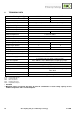
17 TROUBLE SHOOTING The following table shows possible sources of errors and how to remove them (not applicable for the starting-up phase). Display Possible cause Examination/Correction None Fault No supply voltage; Check the supply voltage according to the type plate; ok? Control whether the mains plug is put in correctly; ok? Examine the fine fuses F1, F2 in the cold appliance socket; ok? LED K1 is beaming permanently and temp.
Sample line to the analyser clogged or squeezed; Pollution of the diaphragm pump; Temp. <2°C 4-1.2-ME Cooler switches off the sample gas pump automatically; Cooler defective; No gas flow? Loosen the outlet hose on the analyser side and check on the threaded hose coupling whether sample gas flows; Sample gas does not flow? Clean the clogged line or replace it; Sample gas flows? ok? Loosen the piping on the pump head and examine it (see 15.
18 SPARE PART LIST Wear, tear and replacement part requirements depend on specific operating conditions. The recommended quantities are based on experience and are not binding. Gas Conditioning Unit Version CSS-V (V) Consumables, (E) Recommended Spare Parts and (T) Spare Parts Recommended quantity after operation of [years] Part No. Description C/R/S 1 2 3 Fine filter FPF-2-0,3GF 90 F 0160 Filter element type F-2-0,3GF. Material: glass fiber, porosity: 0,3µ 25 pcs./pack.
Flow meter FM40: 90 A 0015 94 F 0010 94 F 0015 90 A 0018 Flow meter glass for FM40 Measuring range 7-70 l/h air Flow meter glass for FM40 Measuring range 15-150 l/h air Flow meter glass for FM40 Measuring range 25-250 l/h air Viton O-ring 9 for FM40 glass S - 1 1 S - 1 1 S - 1 1 R 2 4 6 R 5 5 5 R R R S S 2 5 5 1 1 2 10 10 2 1 2 10 10 3 1 Miscellaneous: 90 K 6030 Fine fuse 4A T, 5x20mm for CSS...
19 APPENDIX Connecting conductors board CSS-V For further product documentation, please see our internet catalogue: www.mc-techgroup.com Instruction manual peristaltic pump SR25.1, SR25.1-G, document : 3-7.1-ME Instruction manual diaphragm pump series N document : 6-1.2.1-ME Flowmeter FM 40, document : 5-6.1.10 30 Gas sampling and gas conditioning technology 4-1.
Figure 13 4-1.