Manual Gas conditioning series CSS ® Version CSS VC1 and CSS VC2 for 19"- or wall mounting or portable version in carrying case with software version 1.6 Gas sampling and gas conditioning technology 14.
Contents 1 2 3 4 5 6 7 8 General information ..................................................................................................................... 5 Declaration of conformity............................................................................................................ 5 Safety ............................................................................................................................................ 6 Warranty....................................................
18.2.1 Remove pump head Type N 3/5/9 KPE ............................................................................ 44 18.2.2 Replacing the diaphragm Type N 3/5/9 KPE ................................................................... 44 18.2.3 Valve plate change Type N 3/5/9 KPE ............................................................................. 44 18.2.4 Mount pump head type N 3/5/9 KPE ................................................................................ 44 18.2.
Dear Customer, We have organised this manual to enable you to find and understand all the necessary information about the product quickly and easily. If nevertheless you should still have questions regarding the product or its use, do not hesitate to contact us directly at M&C, or your local dealer. Contact addresses can be found in the appendix of this manual. Please also consult our homepage www.mc-techgroup.com for further information about our products.
Headquarters M&C TechGroup Germany GmbH Rehhecke 79 40885 Ratingen Germany Tel: 02102 / 935 - 0 Fax: 02102 / 935 - 111 e-mail: info@mc-techgroup.com www.mc-techgroup.com 1 GENERAL INFORMATION The product described in this manual has been supplied in a safe and tested condition. For safe operation and to maintain this condition, the information and instructions in this manual must be followed.
3 SAFETY Please note the following basic safety precautions when installing, commissioning and operating the device: Before operation and use of the equipment, read the operating manual. The instructions and warnings listed in the operating manual must be followed. Work on electrical equipment must only be performed by qualified personnel in accordance with the regulations currently in force.
5 TERMINOLOGY AND SYMBOLS USED means that death, serious personal injury and/or substantial property damage will result if proper precautions are not taken. DANGER! indicates that death, serious personal injury and/or substantial property damage might occur if proper precautions are not taken. WARNING! means that minor personal injury may result if proper precautions are not taken.
6 INTRODUCTION The gas conditioning CSS-VC unit, either for 19 "- or wall mounting or as a portable unit in carrying case, is a fully pre-assembled compact continuously-operating gas purification system, which, depending on the design, can supply a sample gas volume of max. 1 x 250Nl/h (CSS VC1) or 2 x 150Nl/h (CSS-VC2). Sample gas conditioning units are suitable due to their equipment and additional options for the wide-ranging requirements of continuous gas analysis.
7 APPLICATION With the CSS-VC, fully pre-installed gas conditioning systems are created for continuous use, which can be integrated perfectly into analytical systems. The compact design makes few demands on space. The gas conditioning systems are operational within minutes. This renders time-consuming and expensive procurement of individual components and small parts and their assembly unnecessary. A portable version is also available in a carrying case.
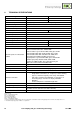
8 TECHNICAL SPECIFICATIONS Gas conditioning series CSS ® Version CSS-VC1 Article number 230V 50Hz Article number 115V/50-60Hz Gas outlet dew point Dew point stability Gas inlet temperature Gas inlet water-vapour saturation Gas flow Ambient temperature Storage temperature Pressure Total cooling capacity ** Number of gas inlets Number of gas outlets Condensate connection Medium connections 01G6050 01G6055 01G6050a 01G6055a Setting range: + 2 ° C .....
8.1 TECHNICAL SPECIFICATIONS FOR THE EXPANSION MODULES Module Communication module Status module Temperature control module Backflush module Article No. 91 B 8620 91 B 8630 91 B 8640 91 B 8650 Power supply 24V DC + - 20% Earthing L <3m - M & C system (RJ-45) L <3m 2 x PT100 (2-wire) L <30 m or 2 x thermocouples L <30 m - - - - - Switching input (Pressure switch) see above - - Max. 100 m 2 x small signal digital output for solid state relay control 24V max.
8.2 OPTIONS Beyond the standard scope of options of this for the CSS-VC, other customised options are possible that cannot be listed in this manual. Description Article No.
Description Article No. Peristaltic pumps for condensate disposal (max. 2 pcs.) Extra charge for mounting a peristaltic pump SR25.2 for condensate disposal, with hoses preinstalled (one required for each gas line) 01G6140 Filter (max. 2 pcs. Front-installed filters and 2 pcs. Universal or aerosol filters) and liquid alarm (max. 2 pcs.
Description Article No.
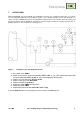
9 DESCRIPTION Figure 2 Dimensions and possible construction CSS-VC.. Fine filter FPF-0, 1GF Flow meter FM40 with and without forked light barrier FA-20mo Multifunctional expandable controller unit TCU Peristaltic pumps SR25.
The current cooler temperature is displayed on the multi-functional control unit TCU mounted on the front panel. The setpoint temperature of the cooler can be set by pressing keys. In the event of warnings or faults, plain text information appears on the display and is also indicated by LEDs (e.g. cooler within the setpoint range and no other alarms - green LED, flow alarm (option) - yellow LED, temperature ± 3° C from the setpoint and humidity alarm (option) - red LED).
11 INSTALLATION INSTRUCTIONS NOTICE! So that the unit is safe and operates reliably, it should be mounted horizontally and without vibration. Only then is proper separation and drainage of the condensate in the heat exchanger of the cooler ensured. The mounting of the gas conditioning unit should take place away from heat sources and be freely ventilated so that there can be no disruptive accumulation of heat.
12 SUPPLY CONNECTIONS Figure 3 Connections in the connection panel of the CSS-VC.. Depending on the version of the CSS-VC, instead of the 11 and 12-pin connector for single alarms, mA output cooler temperature and external sample gas pump control, a 6-pin connector may also be present for group alarm (see Figure 4 ). The sample gas inlet, depending on the version, may also lie directly on the heat exchangers. Figure 4 Connection group alarm In the portable version of the CSS-VC..
12.1 HOSE CONNECTIONS The connection of the sample gas input, depending on the connection type, is directly on the heat exchanger or on the clamping plate. NOTICE! Do not confuse the hose connections. They are marked appropriately. After connecting all the lines, they should be checked to ensure there are no leaks. The condensate connections are made directly to the hose pump.
Mount the connection plate with 2 mounting screws on the rear panel Mount the cover bracket with 2 connection screws on the device cover 12.3 CONNECTION OF THE HEATED LINE WITH ANTIKINK ADAPTER FOR PORTABLE VERSION (ART. NO.
The CSS-VC.. is to be supplied in voltages 230V/50Hz or 115V/50-60Hz (for the circuit diagram see Appendix). Protection is provided as standard with two 4A fuses. These are located in the cold-device socket. The electrical connection is via the 2m long power cord with cold-device connector depending on the mounting of the connection plate either at the back or in the lid of the housing (see Section 12.2). 12.4.1 GROUP CONNECTION ALARM (ART. NO.
12.4.2 CONNECTION OF INDIVIDUAL ALARMS, EXTERNAL PUMP CONTROL AND EXTERNAL COOLER TEMPERATURE DISPLAY (ART. NO. 01G6175) The electrical connection of the individual alarms is via two connectors, depending on the mounting of the connection plate, either on the back or in the lid of the housing. The corresponding 11 and 12-pin connectors are included. The connectors are assigned as follows: Figure 8 Plug assignment for design with individual alarms (Art. No.
On connector X2.1 pin 3+8, 3+9, 3+10, 3+11 respectively, an indicator can be connected that flow alarm messages are present. Since this is a warning message, the yellow LED on the front of the TCU lights up. On X2.1 connector pin 3+4, 3+5, 3+6, 3+7 respectively, an indicator can be connected that liquid alarm messages are present. Since this is an alarm message, the red LED on the front of the TCU lights up. On connector X2.1 pin 1+2, an indicator of cooler temperature can be connected (standard 4-20mA.
12.4.3 CONNECTION OF HEATED LINE FOR PORTABLE VERSION (ART. NO. 01G6190) If, for the portable version in a carrying case, the option temperature controller for heated line (Art. No. 01G6190) is selected, on the rear of the housing of the CSS-VC.. there is a 7-pin connector for connection of heated lines type PSP and PSP 4M and PSP 4M-W. These have at the point of connection and termination a 7-pin connector and a 7-pin socket for connection to the portable gas conditioning unit CSS-VC..
The following steps are to be carried out before initial commissioning: Plug the cold-device connector of the supplied mains connection cable into the cold-device socket for gas conditioning; Connect power cord to the network; Switch on power supply. After the end of the lead time, the gas conditioning unit is ready for operation (green LED on the controller lights up). NOTICE! 13.
14 DECOMMISSIONING NOTICE! The location of the compact conditioning unit must remain frostfree, even during periods when the unit is switched off. On short-term decommissioning of the gas conditioning unit CSS-VC.. no special measures need to be taken. For long-term decommissioning, it is recommended to flush the gas conditioning unit with ambient air or inert gas. A flushing time of 3 to 5 minutes is sufficient under normal conditions. Likewise, condensate residue must be removed from the system.
15.3 ENHANCEMENTS TO THE TCU The TCU can be expanded by up to 4 modules in the range of functions. The modules are plugged together according to requirements and provided for rail mounting. WARNUNG! Before comissioning exclude that for one channel as well internal as external a PT100 is connected. 15.3.1 THE COMMUNICATION MODULE Communication of the TCU with the expansion modules is always with the communication module via the M&C bus. This is therefore the base module for all other modules.
15.3.2 THE TEMPERATURE CONTROL MODULE NOTICE! If the CSS-VC.. is purchased with an external thermostat module, it must be specified at the time of ordering which devices should be regulated (2 probes or 2 heated lines or 1 probe and 1 heated line) so that the controller can be configured accordingly. The temperature control module includes 2 additional thermostats e.g. for control of heated lines or gas sampling probes. Control is by control of external solid-state relays.
15.3.3 THE STATUS MODULE On the status module, by the group alarm message of the TCU a changeover relay and a solid-state relay are connected. These can be used for alarm indication. In addition, external sample gas pumps can be switched off via two further solid-state relays e.g. in the event of an alarm and switched on under good conditions. For external control of the pumps, see Section 12.4.2. Figure 13 14.
15.3.4 THE BACKFLUSH MODULE With the backflush module, on the TCU a backflush programme can be set for gas sampling probes (duration of a backflush pulse, number of backflush pulses, time between backflush pulses, timing of backflush). The programme switches with time delay two solid-state relays with which in turn solenoid valves can be switched, which accordingly release purging air to the gas sampling probe.
16 OPERATION OF THE MULTIFUNCTIONAL CONTROL UNIT TCU In normal fault-free operation, the TCU display shows the current cooling temperature and the green LED is lit constantly when the cooler temperature is within the alarm limits. The bottom line of the display shows "status: OK" or current warning and error messages. Figure 15 Front view of the TCU in normal operation without temperature control module If the external temperature controller module has been purchased with the CSS-VC..
16.1 DISPLAY OF CONTROL TEMPERATURES OR COOLING TEMPERATURE CURVE By 1 x pressing of the arrow button, external temperature control module: the following screen will appear on the CSS-VC.. without an If the external temperature control module was purchased with the CSS-VC.., there is a choice as to which display will appear here after the PRG key has been pressed once. Selection is made with the arrow keys confirmed by pressing the PRG key again (flashing) and .
16.2 CONFIGURE THE SWITCHING ON AND OFF OF THE SAMPLE PUMPS By 2 x pressing of the arrow key appears: and then 1 x pressing of the PRG key, Here it is visible whether the pump is working or not. Using the arrow keys, configured can be selected. By pressing the PRG key again, the following view the pump to be the following view will appear: Using the arrow keys, the parameters to be changed can be selected.
16.3 CONFIGURE BACKFLUSHING By 3 x pressing of the arrow key, then 1 x pressing of the PRG key, appears when the backflush module is connected: Using the arrow keys, the following view the parameters to be changed can be selected. By pressing the PRG key, the parameter can now be changed with the arrow keys and then confirmed with the PRG key discarded with the ESC key or . Here the backflushing of gas sampling probes is determined: Start in = specifies the time of the first backflushing.
Parameters: Start in: Flushing time T1 Dead time Interval T2 On time T3 Off time T4 Pulse number Activation 16.4 Default setting 0d 0h 0m 30s 60s 24h 1s 5s 10 Off Info Max.: 9T 23h 59m Max.: 99m 59s 0-120s Max.: 99s Max.: 99s Is only calculated and cannot be <1 DISPLAY OF EVENTS By 4 x pressing (3 x without backflush module) of the arrow key key, and then 1 x pressing of the PRG the event list appears in which the last 32 error messages and warnings are listed on 8 pages.
16.5 OPERATING DATA By 5 x pressing (4 x without backflush module) of the arrow key (or 1 x pressing of the arrow key following view appears: ) the Here the actual device temperature, the period until the next service warning, the service interval, the software version and serial number are displayed. By pressing the arrow key again, control temperature reappears. 16.
16.7 SETTING SERVICE INTERVAL, LANGUAGE, CONTROL TEMPERATURES AND TEMPERATURE SENSOR TYPES To change service interval, language, control temperatures and temperature sensor types: Disconnect the device from the mains. Hold the PRG key down and switch the device back on until the message to release the key is displayed. The following is displayed (2nd screen Select the parameter key.
After saving or discarding the settings, you will automatically return to the start screen. If the unit is disconnected from the mains voltage while it is in user setup, all changes made are also rejected. The following values can be set: Service interval = (0 (-----) - 365 days/default setting 180Tage/off). After the set time has elapsed, the warning LED (yellow) LIGHTS UP and the following appears in plain text: "Service required".
NOTICE! A thermocouple type must be set only when the temperature control module is connected in conjunction with equipment which do not use a PT100 as a temperature sensor. If a thermocouple type is set, on warming up, an internal check is made whether a heating rate of + 3°C/minute is being reached. If this is not the case, a cable break in the temperature sensor or a thermocouple not connected are assumed. The heating is turned off and the display shows "Thermal Error: 2 (and/or 3) ".
17.2 TEMPERATURE ALARMS FROM COOLER AND TEMPERATURE CONTROL MODULE Error message Lowtemp.: 1 Hightemp: 1 T> Max: 1 Alarm x x x T Max.
This prevents liquid pumped along to the analyser and thus damaging ! The triggered alarm (red LED) must be acknowledged by pressing any key. If the error is not corrected, the error screen comes back after 60s. 17.4 OTHER FAULT AND ALARM MESSAGES Error message Pump-Warn.: 1, 2 Alarm x Warning x Maintenance needed! - x Comm.
The maintenance intervals depend on the process conditions and therefore need to be determined for specific applications. All serviceable parts are mounted in an easily accessible location in the front of the compact gas conditioning unit CSS-VC... Change filter elements of the dust and aerosol filters (FPF-0,1GF/FPF+/universal filter/aerosol filter) when there is too little flow or after visual inspection (see Section 18.
Figure 17 Maintenance of sample gas pump(s) Loosen hoses on the pump head; mount [sic] any existing flow chamber(s) with mounting plate from the stud bolts. 3 N9 KPE N3/5 KPE 4 2 11 9 1 13 14 16 8 7 Figure 18 Sectional drawing N3/5 KPE and N9 KPE NOTICE! 14.1a ME Valve plates, diaphragms and seals should always be replaced at the same time.
The changing of diaphragm(s), valve plates and sealing rings is to be carried out in the following order: Remove pump head Change the diaphragm Change valve plates and sealing rings Mount pump head. Proceed as follows: 18.2.1 REMOVE PUMP HEAD TYPE N 3/5/9 KPE Mark head cover 3 (with metal frame with N3/5), intermediate plate 2 and housing 1 with a felt pen (M). This rules out parts being mounted incorrectly during subsequent assembly.
Check ease of movement of the pump by turning the fan wheel. Move structure diaphragm via fan wheel into the top dead centre (dead point) position. Now hand tighten the screws 4. 18.2.5 CLEANINGTYPE N 3/5/9 KPE On changing valve plates and diaphragm, prior to assembly of the pump head, all parts should be checked for contamination and cleaned if necessary. Wipe the parts as dry as possible with a cloth. Solvents should not be used when cleaning because they may damage the plastic parts.
Figure 19 Components of the peristaltic pump SR25.2 18.3.1 EXCHANGE THE PUMP HOSE WARNING! WARNING! 46 Aggressive media residues possible. On disassembly, repair or cleaning of the hose pump, wear protective glasses and appropriate protective clothing! If you return the hose pump to M&C customer service for repair, we will ask for information concerning the delivered liquid. The pump should be cleaned of hazardous or highly aggressive contaminants prior to return shipment.
Figure 20 Replacing the pump hose Unplug gas conditioning unit from the mains; Remove hose connections on the pump; Squeeze belt using the handles and turn the S-latch clockwise until it stops; Remove the belt and pull the old pump tubing on the slip fittings out of the guides; Squeeze the pressure rollers and see if spring tension exists; if not, change pressure springs (see Section Fehler! Verweisquelle konnte nicht gefunden werden.
Figure 21 Disassembly of pump head and driver Draw the pump head out of the motor shaft Take driver out of the pump head The removal of the springs (4 pcs.) away from the driver is easily possible without the aid of any tools. For this take spring out of the groove near to the shaft bore. Dismount roller axes and change contact pulleys. Take care that axes are not worn out by the springs and have damaged the dent at the axes front end.
Make sure that contact pulleys roll easily on the axis. After remounting the axis with contact pulley into the driver the spring has to be mounted as shown in Figure 22. Please pay attention to the alignment of the dent. Remounting happens in reverse order. NOTE! While mounting pay attention to the fit of ‘rotational axisdriver’ and check that the plunged boss at the shaft bore points to the front of the pump head. Use genuine spare parts only ! 18.3.
19 SPARE PARTS LISTS The wear and spare part requirements depend on specific operating conditions. The recommended quantities are based on experience and are not binding. They refer to the version of CSS-VC.. with a gas line. Gas conditioning version CSS-VC.. (C) Consumable parts, (E) Recommended spare parts (T) Spare parts Article No. FPF-0, 1GF 90F0009 Recommended quantity in operation [years] V/I/T 1 2 Description 3 Filter element type F-0, 1GF material: Glass fibre filtration fineness: 0.
Gas conditioning unit version CSS-VC.. (C) Consumable parts, (E) Recommended spare parts (T) Spare parts Article No. Description Aerosol filter CLF5 90F2005 Filter element type CLF-5 for liquid particulate filters CLF and CLF-5. 90F0040 O-ring (26) for the filter head. Material: Viton. 90F3530 CLF-5/W Spare parts set I, filter frit, membrane filters, flat ring washer, O-ring. Sample gas pump N3/5/9 90P2120 Moulded diaphragm type S3, for N3-N5 KPE, material: Viton/PTFE.
20 APPENDIX Event messages and their meaning CE certification TCU menu Further product documentation can be viewed and accessed on the home page: www.mc-techgroup.com. 52 Gas sampling and gas conditioning technology 14.
Messages that may appear in the list of events and their meanings: Alarms Event message Everything OK T1 alarm T2 alarm T3 alarm T1 low alarm LA1 cable br. LA2 cable br. LA1 alarm LA2 alarm T1-temp> max T2-temp> max T3 temp> max Th2 Error Th3 Error T1-Temp
Cancellation of alarms Event message T1 OK T2 OK T3 OK LA1 OK LA2 OK T1-Temp min T2-Temp> min T3-Temp> min Th3 OK Significance T1 is in the control range or PT100 is OK T2 is in the control range or PT100 is OK T3 is in the control range or PT100 is OK Humidity sensor 1 is OK or has no humidity Humidity sensor 2 is OK or has no humidity T1 <99.
Error and status messages Message SysError Sys OK Comm. error Comm. OK P1 man. On P1 man. Off P2 man. On P2 man. Off P1 ext. On P1 ext. Off P2 ext. On P2 ext. Off P1 auto P2 auto T2 alrm conf. T3 alrm conf. 14.1a ME Significance general internal error. Consult with M&C service department.
Figure 23 56 TCU menu Gas sampling and gas conditioning technology 14.