Instruction Manual Diaphragm Pump Series MP® Version MP30 Gas sampling and gas conditioning technology 6-1.3.
Dear customer, we have made up this operating manual in such a way that all necessary information about the product can be found and understood quickly and easily. Should you still have any question, please do not hesitate to contact M&C directly or go through your appointed dealer. Respective contact addresses are to be found in the annexe to this operating manual. Please also contact our homepage www.mc-techgroup.com for further information about our products.
Content 1 2 3 4 5 6 7 General information ..................................................................................................................... 4 Declaration of conformity ........................................................................................................... 4 Safety instructions....................................................................................................................... 5 Warranty ............................................................
Head Office M&C TechGroup Germany GmbH Rehhecke 79 40885 Ratingen Germany Telephone: 02102 / 935 - 0 Fax: 02102 / 935 - 111 E - mail: info@mc-techgroup.com www.mc-techgroup.com 1 GENERAL INFORMATION The product described in this operating manual has been examined before delivery and left our works in perfect condition related to safety regulations. In order to keep this condition and to guarantee a safe operation, it is important to heed the notes and prescriptions made in this operating manual.
3 SAFETY INSTRUCTIONS Please take care of the following basic safety procedures when mounting, starting up or operating this equipment: Read this operating manual before starting up and use of the equipment. The information and warnings given in this operating manual must be heeded. Any work on electrical equipment is only to be carried out by trained specialists as per the regulations currently in force.
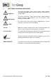
5 USED TERMS AND SIGNAL INDICATIONS DANGER! This means that death, severe physical injuries and/or important material damages will occur in case the respective safety measures are not fulfilled. WARNING! This means that death, severe physical injuries and/or important material damages may occur in case the respective safety measures are not fulfilled. This means that minor physical injuries may occur in case the respective safety measures are not fulfilled.
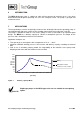
6 INTRODUCTION The MP30 diaphragm pump is suitable for 100% oil-free transport of corrosive gases. It has been dimensioned and designed specifically for use in the analytical sector. The pump is gas-tight and maintenance-free. 7 APPLICATIONS The transported gas remains analytically pure due to the absolutely lubricant-free operating pump. A special diaphragm and valve system ensures freedom from maintenance and a long useful life.
7.1 AMBIENT CONDITIONS The following ambient conditions must be maintained during operation: Ambient temperature range in operation: +5°C .... + 40°C. The pumps must be protected from water and dust. Sufficient ventilation must be provided during operation. The pump type MP30 must not be used in areas subject to explosion hazards or for transporting a potentially explosive medium. The pumps have the degree of protection IP54 as standard. 7.
8 TECHNICAL DATA Diaphragm pump Part No. Voltage supply Power input Power consumption Degree of protection Delivery capacity max. Operating pressure Gas temperature Ambient temperature Storage temperature Gas connections Electrical equipment standard Medium contacted parts Pump head Diaphragms Valves Weight MP30 /230V 02 P 1500 230V 50Hz 10% MP30 /115V 02 P 1500a 115V 60Hz 10% 70W 0,45A 0,7A IP 54 - DIN 40050 7.5 l/min* 0.14 to max. 2.5 bar abs.
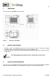
9 DIMENSIONS The dimensions of the MP30 are shown below: Figure 2 10 Dimensions (mm) MP30 RECEIPT AND STORAGE Carefully remove the diaphragm pump and any accessories from the transport packaging immediately upon receipt and check the delivery against the delivery note. Check the contents for possible transport damage and immediately notify the transport insurer of any damage. The diaphragm pump should be stored in a protected, frost-free room.
The safety requirements applicable to the respective media to be transported must be observed. In order to prevent a disturbing accumulation of heat, the pumps should be installed away from sources of heat and freely ventilated. NOTE! NOTE! 11.1 For installation outdoors, the pump must be installed in a protective housing frost-free in winter and sufficiently ventilated in summer. Direct exposure to sunlight must be avoided. Pumps have mechanical moving parts that can induce vibrations.
11.3 PNEUMATIC NOTE! Components to be connected to the pump must conform to the pneumatic data of the pump. Remove safety stoppers from threaded gas connections (thread size G1/8”). Accessories such as threaded hose couplings must be screwed into the threaded connection with sealing tape (the use of sealing tape is unnecessary when using M&C couplings). Connect suction and pressure pipe.
12 COMMISSIONING Prior to commissioning, system and process-specific safety measures must be observed. For the media to be transported, the respective safety requirements and measures must be taken into account. Prior to using a medium, the compatibility of the materials of the pump head, diaphragm and valves with the medium must be verified (for materials, see technical data). The following steps must be carried out for commissioning: The pumps must not start against pressure or vacuum.
13 DECOMMISSIONING NOTE! The site of installation of the diaphragm pump must remain frostfree also during the time when the unit is switched off. No further particular measures are required for decommissioning. WARNING! When transporting aggressive media, purging the pump with inert gas under atmospheric conditions is recommended prior to decommissioning. If there is no risk of explosion, air can also be used for this purpose. Aggressive media residues possible.
14.1 REPLACING DIAPHRAGMS, VALVE PLATES AND SEALING RINGS Figure 4 shows a sectional drawing of the pump head.
Remove support cup 9, adjusting washers 10 and cup spring 11 from thread bolt of diaphragm and clean if necessary. Fitting the new diaphragm takes place in reverse order. The edge of the cup spring must point towards the diaphragm. NOTE! Replacing valve plates and sealing rings: Loosen screws 7 and separate head cover 4 from intermediate plate 1. Remove valve plates 2 and sealing rings 3 from intermediate plate.
16 TROUBLESHOOTING Before carrying out any work on the pump, it must be safely isolated from the supply and disconnection from the supply verified. The following instructions for troubleshooting are hierarchically structured, i.e. to be used in the specified order. Problem/Indication Possible cause Check/Remedy No system voltage available. Check system voltage. Check mains cable for Pump does not tightness. transport Connections or pipes are blocked.
If none of the specified faults can be located, despite the pump not operating correctly, the pump should be returned to M&C for examination. NOTE! 17 When sending diaphragm pumps for repair to M&C Customer Service, information about the transported medium is required. Our workshop should be informed in particular about aggressive media. Where pumps have been used for transporting dangerous or highly aggressive gases, these should be cleaned prior to being returned.