
Operator's manual


12
Gas sampling and gas conditioning technology 6-1.3.5-ME
11.3 PNEUMATIC
NOTE!
Components to be connected to the pump must conform to the pneumatic
data of the pump.
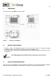
Remove safety stoppers from threaded gas connections (thread size G1/8”).
Accessories such as threaded hose couplings must be screwed into the threaded connection with
sealing tape (the use of sealing tape is unnecessary when using M&C couplings).
Connect suction and pressure pipe.
NOTE!
Do not interchange hose connections for sample gas inlet and outlet; the
connections are appropriately marked.
After connecting all pipes, they must be checked for tightness.
When connecting the hoses to optional threaded hose couplings, the following should be noted:
NOTE!
The tightness of the connection can only be ensured when the connecting
hose has a straight terminating edge (use of a hose cutter).
Loosen the swivel nut of the clamping ring by turning anticlockwise; it must be ensured that the nut
is carefully removed from the coupling, so that the clamping ring lying loosely in the clamping ring is
not lost.
Slide the swivel nut on to the connecting hose.
Slide the clamping ring with the thicker part pointing towards the nut on to the connecting hose.
Fit the hose on to the supporting nipple in the coupling;
Tighten the swivel nut hand-tight.
The hose is not connected non-slip and pressure-proof.
Optional threaded couplings for DN 4/6 or DN 6/8 can be obtained through M&C
Route the suction and pressure pipe so that no condensate can flow into the pump.