
Operator's manual


15
Gas sampling and gas conditioning technology 6-1.3.5-ME
14.1 REPLACING DIAPHRAGMS, VALVE PLATES AND SEALING RINGS
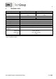
Figure 4 shows a sectional drawing of the pump head.
1
2
3
4
5
6
7
8
9
10
11
15
Positioning
the cup
spring 11
Figure 3 Section drawing of pump head MP30
Replacing the diaphragm:
Mark position of pressure plate 15, head cover 4, intermediate plate 1 and housing 14 by making a
continuous line with a felt-tip pen.
Loosen four head screws 5.
Remove pressure plate 15, head cover 4 and intermediate plate 1 from pump housing.
Loosen four fixing screws in impeller cover 13 and remove.
Bring diaphragm 8 into top position by turning impeller 12;
Unscrew diaphragm on side edges anticlockwise.
1 Intermediate plate
2 Valve plate
3 Sealing ring
4 Head cover
5 Screw
6 Screw cap
7 Screw
8 Diaphragm
9 Supporting cup
10 Adjusting washers
11 Cup spring
12 Impeller
13 Impeller cover
14 Housing
15 Pressure plate
M Mark
15
14
13
12
1
4
5
6
M