
Operator's manual


16
Gas sampling and gas conditioning technology 6-1.3.5-ME
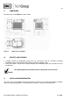
Remove support cup 9, adjusting washers 10 and cup spring 11 from thread bolt of diaphragm and
clean if necessary.
Fitting the new diaphragm takes place in reverse order.
NOTE!
The edge of the cup spring must point towards the diaphragm.
Replacing valve plates and sealing rings:
Loosen screws 7 and separate head cover 4 from intermediate plate 1.
Remove valve plates 2 and sealing rings 3 from intermediate plate.
Inspect valve seat, intermediate plate or ribbed cover for cleanliness and damage and replace if
necessary.
Fit new valve plates 2 (suction and pressure side or top and bottom side are identical); check for
correct position by lightly moving the valve seat.
Fit sealing rings 3 in intermediate plate 1.
Join head cover 4 and intermediate plate 1 together (felt-tip pen mark must be in alignment) and
check centred seat through lateral movement.
Fix head cover 4 and intermediate plate 1 in place with screws 7.
Fitting pump head:
Place intermediate plate 1 and head cover 4 according to felt-tip pen mark M on pump housing.
Also place pressure plate 15 in position (mark) and lightly tighten crosswise with screws 5 and cup
springs.
Check pump for smooth operation by turning impeller 12.
Tighten screws 5 crosswise until cup springs rest flat against pressure plate.
15 CLEANING
When replacing the valve plates and diaphragms, all parts must be checked for fouling before
assembling the valve head and cleaned if necessary. If available, the parts should carefully be blown
out with compressed air.