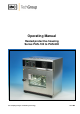
Operating Manual Heated protective housing Series PAS-100 to PAS-500 Gas sampling and gas conditioning technology 10-5.
Dear customer, we have made up this operating manual in such a way that all necessary information about the product can be found and understood quickly and easily. Should you still have any question, please do not hesitate to contact M&C directly or go through your appointed dealer. Respective contact addresses are to be found in the annexe to this operating manual. Please also contact our homepage www.mc-techgroup.com for further information about our products.
List of Contents 1 General information....................................................................................................................... 4 2 Declaration of conformity ............................................................................................................. 4 3 Safety instructions ........................................................................................................................ 5 4 Warranty .....................................................
Head Office M&C TechGroup Germany GmbH Rehhecke 79 40885 Ratingen Germany Telephone: 02102 / 935 - 0 Fax: 02102 / 935 - 111 E - mail: info@mc-techgroup.com www.mc-techgroup.com 1 GENERAL INFORMATION The product described in this operating manual has been examined before delivery and left our works in perfect condition related to safety regulations.
3 SAFETY INSTRUCTIONS Please take care of the following basic safety procedures when mounting, starting up or operating this equipment: Read this operating manual before starting up and use of the equipment. The information and warnings given in this operating manual must be heeded. Any work on electrical equipment is only to be carried out by trained specialists as per the regulations currently in force.
5 USED TERMS AND SIGNAL INDICATIONS DANGER! This means that death, severe physical injuries and/or important material damages will occur in case the respective safety measures are not fulfilled. WARNING! This means that death, severe physical injuries and/or important material damages may occur in case the respective safety measures are not fulfilled. This means that minor physical injuries may occur in case the respective safety measures are not fulfilled.
6 INTRODUCTION A big problem of the extractive continuous gas analysis are the escort substances of the gas, such as water vapour as well as gas components that produce corrosive acids in connection with condensed water vapour. In order to realise a maintenance-free resp. “hot” measurement, the condensation of water vapour and gas components within the gas conditioning must be prevented. The solution for this problem are the heated M&C sample conditioning units PAS.
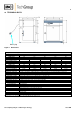
10 TECHNICAL DATA Mains plug Figure 1 Dimensions Heated protective housing Series PAS Assembly interior: Width A mm Height B mm Depth C mm External dimensions Width D mm Height E mm Depth F mm Weight empty kg Ventilator Power consumption Power supply Electrical connection Material of cabinet Mounting Temperature control Temperature display Temperature limit Temperature selection Operating temperature Ambient temperature Case protection Options: PAS-100 PAS-200 PAS-300 PAS-400 PAS-500 320 240 175
11 APPLICATION Heated M&C sample conditioning systems are used where increased and constant operating temperatures are necessary for the analysis of gases or liquids. The large M&C product range of heatable components, in connection with the heated PAS-... protective housing, allows you to solve problems specific to your applications. 12 DESCRIPTION The conditioning components are housed in the protective cabinet (wall mounting) made of stainless steel, which is heat insulated on all sides.
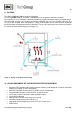
13 AUFBAU The devices PAS100 - 300 have natural ventilation. In series PAS400 – 500 air circulation is provided by a fan on the back wall of the chamber. The incoming air (1) is warmed in a preheat chamber (2) in both convection and fan-circulation ovens. The preheated air enters the chamber (4) through ventilation slots (3) in the chamber side wall. The fan (5) on the chamber back wall produces a large air throughput and a more intensive horizontal forced circulation compared with natural convection.
13.2 MATERIAL QUALITY The external casing and working chamber is out of stainless steel 1.4301 which features high strength, optimum hygienic properties and corrosion resistance against many (not all) chemicals (warning against e.g. chlorine compounds). The oven load has to be checked carefully for its chemical compatibility with the above materials. 13.3 ELECTRICAL EQUIPMENT Operating voltage see label 50/60 Hz Current rating see label Protection Class 1, i.e.
15.1 INSTALLATION FACILITIES (ACCESSORIES) The heated protective housing can be placed on the floor or on a bench (working surface). It is important that the oven is set up accurately horizontally; the door may have to be adjusted (see chapter 13 „Maintenance“). Do not place the device on a readily inflammable support surface! WARNING! The spacing from the back of the heated protective housing to the wall should be at least 15 cm.
Figure 4 Wall bracket 16 OPERATING 16.1 OPERATING THE DOOR The door is opened by pulling on the door handle. The door is closed by the door handle being pushed in. Figure 5 Operating the door 16.2 CONTROLS AND INDICATIONS Figure 6 Controls and indications Gas sampling and gas conditioning technology 10-5.
16.3 SWITCHING ON The heating is switched on by pressing the push/turn control. Heating switched off. The push/turn control is using the pushed in and protected against damage Heating switched on and can be operated push/turn control and the SET key. 16.4 SETTING AIR CHANGES Moving the air slider opens and closes the air valve to control the supply and discharge of air. Air valve closed Air valve open 16.
16.7 NORMAL OPERATION In this operating mode the heated protective housing operates continuously and heats and controls to the set temperature. On the PAS-400 – 500 the fan is running continuously. Setting the temperature: Hold down the SET key and set the required temperature set point with the push/turn control. After the SET key has been released the display flashes briefly the temperature set point.
16.9.2 MONITOR RELAY In addition to mechanical temperature protection the heated protective housing is provided with an electronic monitor relay. If a fault occurs during operation or if the selected set point temperature is exceeded by 10°C the monitor relay switches over the heating to this temperature in emergency mode. The alarm symbol is flashing as warning.
Figure 8 Arrangement of the temperature sensor There must be no possibility of the formation of inflammable gas/air mixtures either within the oven chamber or in the immediate surroundings of the equipment. Large amounts of dust or corrosive fumes inside the oven chamber or in the surroundings of the equipment may produce deposits within the oven and lead to short-circuits or damage the electronics.
The top part (1) of the door hinge can, after releasing the 2 screws (2) at the top or bottom of the door, be moved slightly in the direction of the arrow. The door can be adjusted after releasing the socket screw (3) and rotating the eccentric (4) by means of a screwdriver. NOTE ! Screw (3) is locked with locking varnish. It can be released by a sharp tug using a hexagon socket key. Apply more locking varnish to screw (3) and tighten it.
21 OPTION LOW TEMPERATURE ALARM The heated protective housing PAS can be controlled by a low temperature alarm contact. The sensor is fixed to the ceiling of the inner oven. The controller of this thermostat is installed in the top of the oven under the top cover. The range of temperature setting is from 100 – 180°C. The standard controller setting is at +150°C. The contact is closed during normal operation and opens when the temperature decreases <150°C. The contact rating is 230V AC, 16A.
Figure 10 Wiring plan for low temperature alarm Gas sampling and gas conditioning technology 10-5.