LANGUAGE DESCRIPTION EN OPERATING INSTRUCTIONS Manual Version V01.00-REV01.
RC-R-100 Table of Contents Table of Contents 1 Description .............................................................................................................................................................. 5 1.1 1.1.1 Preface .............................................................................................................................................. 5 1.1.2 Safety Instructions ................................................................................................
Table of Contents 2.6.2 RC-R-100 Touch Probe in Mono-directional Mode .......................................................................................... 31 2.7 Temperature Measurement .......................................................................................................................... 32 2.8 Ultrasonic measurement............................................................................................................................... 33 2.9 Laser scanning ..........
RC-R-100 1 Description Description 1.1 General 1.1.1 Preface The instructions and safety instructions in this manual have to be strictly observed to guarantee a safe and reliable function of the receiver and to avoid personal and material damage. The meaning of the symbols related to the safety instructions is described in the table below: CAUTION NOTICE INFORMATION 1.1.2 CAUTION indicates a hazardous situation that, if not avoided, could result in injury.
Description 1.1.3 RC-R-100 Validity This document is valid for the hardware available at the creation date of this document. The manufacturer reserves the right to make technical modifications. 1.2 Purpose The radio-wave receiver RC-R-100 is used for reception of the measuring signals from the touch probe system RWP20.50-G and from the laser scanner LS-R-4.8.
RC-R-100 1.3 Description Declarations and Approvals 1.3.1 Europe and UK (EC and UKCA Declarations of Conformity) The EU and UKCA Declarations of Conformity can be found at the end of these operating instructions. If required, a copy of the signed original declarations of conformity may be requested from the address given on the back cover. 1.3.2 USA (FCC Declaration) This device complies with Part 15 of the FCC.
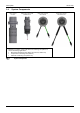
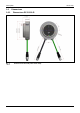
Description 1.4 RC-R-100 System Components Laser scanner LS-R-4.8 Radio-wave touch probe RWP20.50-G* Radio-wave receiver RC-R-100-R * Modular touch probe system with different measuring unit options for various measuring applications: • Mechanical measuring units (PP41.00, MY21.00, HPP41.10) • Temperature measuring unit (TP44.10) • Ultrasonic measuring unit (UTP47.
RC-R-100 1.5 Technical Data 1.5.1 Technical Data RC-R-100 Transmission frequency Transmission/reception range Power supply Weight Temperature range Material Sealing Installation(TD) Connecting cable 1.5.2 Description 2400-2483.5 MHz (2.4 GHz) 5.18-5.24 GHz (WLAN 5GHz) (20 MHz channels 36, 40, 44, 48) Up to 15 m 12 - 30 VDC, max.
Description 1.6 1.6.
RC-R-100 1.6.
Description 1.
RC-R-100 1.8 Description Transmission and Reception Area INFORMATION The transmission/reception ranges shown below only apply under optimum operating conditions. For a secure signal transmission, measurement system and receiver must be located in the transmission area of the other device. The range for a secure signal transmission is up to 15 m. It is recommended that the receiver is arranged so that the measurement system is within an angle of -30° to 30° relative to the receiver (see Fig. 5).
Description 1.9 1.9.
RC-R-100 Order Number H00028050 H00028051 H00028052 H00028053 Description Description Illustration Sensor cable (M12/F12-W-L05) with plug and wires (L=5 m/16.4') Sensor cable (M12/F12-W-L10) with plug and wires (L=10 m/32.8') Sensor cable (M12/F12-W-L15) with plug and wires (L=15 m/49.2') Sensor cable (M12/F12-W-L30) with plug and wires (L=30 m/98.4') H00028047 Ethernet cable (L=5 m/16.4') H00028048 Ethernet cable (L=10 m/32.8') H00028049 Ethernet cable (L=30 m/98.
Description 1.9.3 RC-R-100 Spares Order Number Description 5191 Cap head screw DIN EN ISO 4762, M4x25 3826 Cap head screw DIN EN ISO 4762, M5x12 2012 Spring washer DIN128 0899 Nut DIN EN 24032, M4 6204 Gasket (Viton) 6282 Threaded cable gland M25x1.5 6283 Nut M25x1.5 Mounting bracket with mounting parts: 2x Cap head screw DIN912 M4x25 (5191) 95.
RC-R-100 2 Operation Operation 2.1 Mounting 2.1.1 General Instructions for Mounting NOTICE Risk of transmission faults! • • • Never mount the receiver in the vicinity of electrical components. Mount the receiver as close as possible to the touch probe. Preferably mount the receiver isolated from the machine for optimum reception.
Operation 2.1.2 RC-R-100 Mounting RC-R-100-R-PT Gasket (Viton) (6204) Cap head screw (4x) DIN EN 4762, M4x25 (5191) Network cable (2 m) with protection tube Nut M25x1.5 (6283) Spring washer DIN128 (4x) (2012) Nut (4x) DIN EN 24032, M4 (0899) Mounting RC-R-100-R-PT 18 Connecting cable (2 m) with protection tube Threaded cable gland M25x1.
RC-R-100 2.1.3 Operation Mounting RC-R-100-R / RC-R-100-R-PT with Mounting Bracket (machine wall, internal) Nut (2x) DIN EN 24032, M5 (0852) Spring washer DIN128 (2x) (3478) Cap head screw (2x) DIN EN 4762, M5x12 (3826) Mounting bracket, adjustable 95.
Operation 2.1.
RC-R-100 2.2 Operation Connection 2.2.1 2.2.1.1 Overview over machine control/PC connections Connections when using the laser scanner LS-R-4.8 Radio-wave receiver RC-R-100 Sensor cable 5 m (H00028050) 10 m (H00028051) 15 m (H00028052) 30 m (H00028053) Laser scanner LS-R-4.
Operation 2.2.1.2 RC-R-100 Connections when using the radio-wave touch probe RWP20.50-G Radio-wave receiver RC-R-100 Sensor cable 5 m (H00028050) 10 m (H00028051) 15 m (H00028052) 30 m (H00028053) Connections when using the radio-wave touch probe RWP20.50-G 22 Radio-wave touch probe RWR20.
RC-R-100 2.2.2 Operation Electrical connection to the machine control INFORMATION Wiring diagrams for specific controls and measurement-system combinations are available upon request. NOTICE Risk of material damage! • First set the output signals (refer to chapter 2.3.1), then connect pins 4, 5 and 6. 2.2.2.1 Sensor cable pin assignment (receiver) Pin Description 1 GND 0 V* 2 12-30 V* 3 ON/OFF (Bidi) / GND 0 V (Mono) 4 Probe (max. 40 mA) 5 READY (max. 40 mA) 6 LOW BATTERY (max.
Operation RC-R-100 2.2.2.2 Overview of wire colours for the sensor cable Pin Description Colour 1 GND 0 V* brown 2 12-30 V* blue 3 M code ON/OFF (Bidi) / GND 0 V (Mono) white 4 Probe (max. 40 mA) green 5 READY (max. 40 mA) pink 6 LOW BATTERY (max.
RC-R-100 2.2.2.5 Operation Output Circuit, Temperature measurement Pin 10 RC-R-100 Control (A/D converter) Internal Signal Pin 10 Temperature Input CNC 5-14 mA Shunt max. 600 Ώ Current source or Control (digital input) Ultrasonic Input CNC max. 20 mA Output Circuit, Temperature/Ultrasonic Measurement Pin 10 2.2.2.6 Signal Connection INFORMATION Temperature measurement is not possible with signal connection! INFORMATION Signal connection is recommended, if the machine control cannot check READY.
Operation 2.3 RC-R-100 Output Signals 2.3.1 Setting the Behaviour of the Output Signals The behaviour of the output signals is set using a rotary coding switch on the read of the device. The setting only takes effect after a restart of the receiver. Rotary coding switch S1 Set output signal Setting of output signal with the rotary coding switch 2.3.
RC-R-100 2.3.3 Operation Signal Diagram for Touch Probe in Bi-directional Mode Example of output signal "0" (Heidenhain/Siemens) 1 2 3 4 5 5.
Operation 2.4 RC-R-100 Pairing a Measuring System ("Pairing Mode") Each RC-R-100 receiver is able to control the addresses of 8 bi-directional measurement systems (Activation code A-H). These measurement systems are assigned in the so-called "Pairing mode". Pairing mode is started by the measurement system and the precise procedure for assignment is described in the operating instructions for the relevant measurement system. 2.4.
RC-R-100 2.6 Operation Activation/Deactivation of the Measuring System 2.6.1 Touch probe/laser scanner in bi-directional mode INFORMATION In "ERROR" mode, the receiver scans the entire frequency range available to it for interference and internally evaluates the available frequency bands for their quality.
Operation RC-R-100 The touch probe RWP20.50-G and the laser scanner LS-R-4.8 can be activated and deactivated by the radio-wave receiver RC-R-100. Once the M code has been set, the relevant measurement system will be activated in < 1 s* and deactivated again < 1 s* after reset. When activating the laser scanner LS-R-4.8, an additional 10 seconds are required to establish the WLAN connection for measurement data transmission.
RC-R-100 2.6.2 Operation Touch Probe in Mono-directional Mode INFORMATION Mechanical self activation of the probe. • 1. Activation time <0.35 s Switching ON the touch probe: 1.1 Load probe into spindle. 1.2 Probe switches ON by mechanical ON-OFF method: • AZ → Pullforce at SK-pullstud • ME → Switch ON mechanism in HSK • WS→ Cooling water supply or spindle air blast (Description of mechanical switch ON methods in the respective operating instructions) Probe transmits Wake-Up signal to receiver.
Operation 2.7 RC-R-100 Temperature Measurement Temperature Probe RWP20.50-G-TP RC-R-100 Pin 10 (Analog OUT) Temperature Measurement Measuring Range 5 - 50°C (5-14 mA) 41 - 122°F (5-14 mA) Resolution ∆ 0.1°C = 20 µA ∆ 0.182°F = 20 µA Temperature Temperature Calculation: (x mA * 5°C/mA) - 20°C = Temperature in °C (x mA * 9°F/mA) - 4°F = Temperature in °F ∆0.1°C 20 µA = ∆0.1°C 20 µA = ∆0.
RC-R-100 2.8 Operation Ultrasonic measurement RC-R-100 Ultrasonic Touch Probe RWP20.50-G-UTP Pin 7 (Serial IN) Pin 8 (Serial CLOCK) Pin 10 (Serial OUT) D = Material thickness of test piece Ultrasonic signal (transmitted) Ultrasonic signal (reflected) D Ultrasonic measurement Accuracy and Measuring Range: The accuracy and measuring range of ultrasonic measurement depend on the material to be measured, the calibration and the selected probe head.
Operation 2.9 RC-R-100 Laser scanning During laser scanning, data is transmitted from the laser scanner to the radio-wave receiver on 2 paths. The laser scanner is activated/deactivated by the receiver, and the operating parameters ("READY", "PROBE", "LOW BATTERY") of the laser scanner are transmitted to the receiver via a 2.4 GHz radio-wave connection. The scan data (measurement data) are transmitted via an additional WLAN connection, which is automatically set up once during pairing (see chapter 2.4.
RC-R-100 Operation 2.10 Optical Indicators LowBat Network status Status Transmission power LED Indicators of RC-R-100 2.10.
Operation RC-R-100 2.10.2 Transmission Power Indicator Transmission/Reception Power Indicator Poor Optimum 2.10.